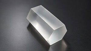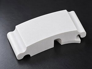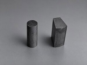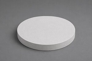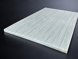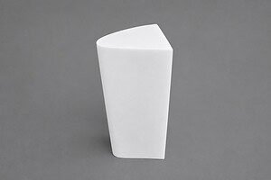
A solid fused quartz block. The task is to cut a defined contour through the block, lift the inner shaped part out intact, and leave the surrounding material usable — not fractured, not chipped along the inner wall, not with microcracks propagating back into the parent block.
This is not slicing. It is not ring cutting. In slicing, the entire kerf exits the workpiece on both sides; in ring cutting, the geometry is a continuous closed curve with no sharp direction changes. Quartz block contour cutting introduces two conditions that neither of those cases does: the diamond wire has to follow a path with direction changes along its length, and at the end of the cut the inner section becomes a free body before the wire finishes its final pass. Both conditions concentrate stress at specific points on a brittle material with a fracture toughness around 0.75 MPa·m⁰·⁵.
This case walks through how VIMFUN approaches contour cutting on fused quartz blocks, which parameters the process operates inside, and why controlled feed and secure support dominate the outcome.
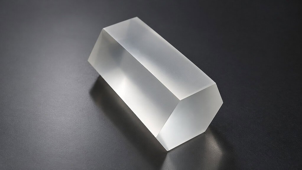
The Application: Contour-Shaped Fused Quartz Parts
Fused quartz carries a specific property set that is hard to substitute: near-zero coefficient of thermal expansion (0.55 × 10⁻⁶/°C), broad UV-to-IR transmission, chemical purity, and dimensional stability through aggressive thermal cycling. Fused quartz material properties are documented in detail across the materials literature. For contour-shaped parts cut out of a parent block, those properties translate into applications where the finished geometry is not axisymmetric:
- Optics — custom-shaped windows, aperture plates, prism blanks, and non-circular optical elements
- Semiconductor fixtures — chamber inserts, isolation plates, and process-chamber tooling cut to equipment-specific profiles
- Photonics — mounts and brackets for laser and beam-path components with application-specific outlines
- Lab precision parts — custom cells, holders, and sample stages where off-the-shelf geometry does not match the measurement setup
In each case the cut edge is a functional surface. It is either a reference edge for downstream assembly or a surface that will see subsequent grinding and polishing. What the wire leaves behind sets the starting condition for everything after it.
The Challenge: Quartz Block Contour Cutting at Direction Changes and Breakthrough
Three mechanics drive the difficulty of quartz block contour cutting, and all three are specific to the contour geometry — they do not appear with the same weight in straight slicing.
Brittle fracture risk at direction changes. When the wire path turns, the lateral force vector at the cut interface rotates with it. On a brittle material, abrupt vector changes concentrate stress at the inside of the turn. If the feed rate is not reduced through the turn, that stress spike can initiate chipping at the kerf wall or, worse, start a microcrack running away from the kerf into either the inner part or the parent block. The tighter the inner radius, the sharper the stress concentration.
Breakthrough risk at the end of the cut. As the wire approaches the final millimeter of its contour path, the inner section is nearly separated from the parent block. The remaining bridge of material carries the full support load of the inner part. When that bridge thins past a threshold, the inner section begins to shift — gravity, residual stress in the quartz, or lateral force from the wire itself can move it. On fused quartz, any uncontrolled motion at this moment translates into chipping on the final length of kerf and risk of crack initiation on both the inner part and the parent block.
Chip control along a varying contact arc. On a contour, the contact arc between the diamond wire and the quartz changes as the wire follows the path. On a straight segment, the arc is defined by the block thickness. Approaching a tight curve or a direction change, the effective engagement geometry shifts and chip evacuation from the kerf becomes less predictable. Debris that is not cleared from the active kerf becomes a secondary abrasion source — scoring the kerf wall and increasing surface damage.
None of these makes the cut impossible. They set the constraint envelope the process has to operate inside.
The Approach: SVI60-60 Platform and Diamond Wire from the Reference Range
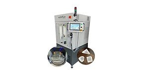
VIMFUN runs quartz block contour cutting on the SVI60-60 endless diamond wire saw, a vertical two-axis machine whose function set explicitly includes contour cutting, inner hole cutting, rotary cutting, and tilt cutting — the geometry flexibility that a shaped-part job out of a solid quartz block requires. The saw is paired with electroplated diamond wire from the fused-quartz reference range in the VIMFUN parameter table.
Rather than quote a single wire diameter or wire speed as if it were the universal answer, the honest framing is: the parameter table gives a range for fused quartz, and the specific value inside that range is picked based on the actual workpiece thickness and the tightness of the contour before a trial cut is performed. A thin block with a loose outline sits at one end of the range; a thick block with tight inner radii sits at the other.
Wire selection. The reference range for fused quartz is 0.55 to 0.8 mm electroplated diamond wire. Thinner wire in the lower end of that range keeps kerf width narrow and reduces cutting force per unit area, which helps on tighter contour radii. Thicker wire adds mechanical stiffness and tolerates higher feed on heavier sections. The endless-loop format (see electroplated diamond wire loop) presents consistent diamond coverage across the full cut, which matters on a contour cut that may run long enough for wire wear gradients to otherwise show up as surface-quality drift between the start and end of the path.
Fixturing. Before cutting, the block is mounted with soft tooling that spreads clamping force uniformly across the parent faces. Point loads on fused quartz are a crack-initiation risk even before the wire starts. The fixturing also has to anticipate the breakthrough moment: the inner part needs secondary support so that when the final bridge thins, the inner section cannot shift under its own weight or under residual lateral force from the wire.
Process Parameters
| Parameter | Reference range |
|---|---|
| Machine | VIMFUN SVI60-60 Vertical Endless Diamond Wire Saw |
| Wire diameter | 0.55 – 0.8 mm electroplated diamond wire |
| Wire speed | 30 – 60 m/s |
| Feed rate | 2 – 10 mm/min |
| Coolant | White mineral oil, continuous recirculation |
| Workpiece support | Soft tooling, uniform clamping, secondary support for the inner section |
These are reference ranges from VIMFUN’s parameter table for fused quartz. Specific values are selected within these ranges based on workpiece thickness and contour geometry, then verified through a trial cut before production. For how the three main dynamic parameters interact and the tradeoffs between them, see wire speed, tension, and feed rate.
On the ranges. The 2–10 mm/min feed window is wide for a reason. On a straightforward outline cut through a 20 mm block, the feed can sit comfortably in the upper half of the range. On a 60 mm thick block with tight inner radii, the trial cut will typically land in the lower half, with further reduction programmed into the direction-change segments. Wire speed interacts with coolant delivery: higher wire speeds move more coolant through the kerf but also increase the heat generation rate. Both are tuned together, not independently.
Coolant. White mineral oil is the recommended coolant for fused quartz cutting on the SVI60-60. It carries diamond wire wear characteristics that are well understood on silicates, lubricates the wire-material interface, and keeps the kerf flushed of debris. Continuous recirculation with filtration is standard — the goal is to keep particle concentration low enough that debris from earlier in the cut cannot re-enter the active kerf as a secondary abrasion source.

Why Controlled Feed and Secure Support Matter at Direction Changes and Breakthrough
The two moments that decide whether a quartz block contour cutting job succeeds are the direction change and the breakthrough. Both are governed by the same underlying mechanic — stress redistribution — and both respond to the same two levers: feed rate and workpiece support.
At a direction change. As the wire path turns, the lateral component of cutting force shifts. If the feed rate is held constant through the turn, the wire has less time to clear material from the new path direction, and the force vector loads a kerf wall that was not previously bearing it. On fused quartz with low fracture toughness, that transition is where microcracks initiate. Reducing feed through the turn gives the wire time to establish a clean kerf in the new direction and keeps the per-cycle force spike below the chipping threshold. On tighter inner radii, a programmed feed reduction is not optional — it is the mechanism that keeps the cut on specification.
At breakthrough. The last millimeter of the cut is where the inner section’s support condition changes faster than anywhere else on the path. The bridge of remaining material thins; the stiffness holding the inner part in place drops; eventually the inner part becomes a free body still being touched by the wire. If the fixturing has not already placed a secondary support under the inner section before this moment, any downward or lateral shift transfers into the wire-material interface as an unplanned load. On brittle quartz, unplanned load at the kerf edge means chipping on the finished contour of both the inner part and the parent block — exactly the surfaces that have to come out clean.
The approach VIMFUN uses to control both: reduce feed in the final segment of the cut, verify secondary support is engaged before the bridge thins past the safe threshold, and keep coolant flow through the kerf uninterrupted so that heat and debris do not add stress at the critical moment.
Post-Cut Inspection: Part Separation, Caliper Check, Edge Review
Once the contour cut is complete, the inner section is separated from the surrounding block. On a clean cut, this is a gentle operation — the wire has done the work, and the two pieces come apart without force.
Inspection then runs in three steps:
- Dimensional check. A caliper is used to measure the inner section against the specified contour dimensions. Deviations within tolerance confirm the cut path tracked the program.
- Edge inspection. Visual review of the kerf edges on both the inner part and the parent block. Chipping, if any, is measured. On well-dialed parameters within the reference range, edge chipping stays within specification without secondary rework.
- Cut surface inspection. The kerf surfaces themselves are reviewed for surface finish and the presence of scoring, roughness bands, or evidence of debris marking. Clean, uniform cut surfaces indicate the coolant and feed were correctly matched to the geometry.
Dimensional accuracy, edge condition, and cut-surface quality together determine whether the parts are ready for the next process step or need remediation before downstream grinding and polishing.
Known Limitations
Not every quartz block contour cutting job sits inside the reference ranges above. The envelope has edges that are worth stating:
- Very tight inner radii — radii approaching the wire diameter are feasible but reduce the usable feed-rate window dramatically. Below a certain radius-to-wire-diameter ratio, a different wire gauge or a modified path strategy is required.
- Extreme block thickness — blocks substantially thicker than typical production work extend contact-arc engagement and may push the useful feed rate below the lower end of the reference range. Cycle time climbs accordingly.
- Deeply re-entrant contours — contours with sharp inward returns can trap debris in the kerf. These cases often need adjusted coolant delivery or a staged cut strategy rather than a single continuous path.
- Material heterogeneity — bubbles, inclusions, or stress zones in the parent block change local fracture behavior. A trial cut is the only reliable way to catch this before production.
The honest version of the process description: the reference ranges cover most quartz block contour cutting applications, and the trial cut is where the specific values inside those ranges are confirmed for the specific workpiece. For the broader diamond wire saw platform behind this process, see wire saw cutting overview. For additional context on quartz glass applications and material behavior, see AZoM on quartz glass applications.
Industries and Applications
Quartz block contour cutting serves several categories of customer:
- Optics manufacturers — custom window shapes, aperture plates, and non-circular optical blanks cut from fused quartz stock
- Semiconductor fixture suppliers — chamber inserts and process-chamber components in application-specific profiles
- Photonics integrators — mounts, brackets, and beam-path parts cut to equipment-specific outlines
- Laboratory precision part makers — custom cells, sample stages, and holders where off-the-shelf geometry does not fit the measurement workflow
For related quartz cases on different geometries, see our large quartz glass ring cutting case study covering a 420 mm fused quartz ring, and our hexagonal bore quartz tube cutting case study covering a non-circular internal profile cut through a tube wall.
Can We Cut This for Your Application?
If your application calls for a shaped part cut from a fused quartz block — with the surrounding material preserved and clean edges on both pieces — the process approach described here applies. Wire diameter, wire speed, feed rate, and coolant settings sit inside the reference ranges above and are dialed in through a trial cut for your specific geometry.
To get a feasibility assessment, send us:
- Material and grade — fused quartz, synthetic quartz, or specific optical/semiconductor grade
- Workpiece geometry — block dimensions and contour drawing with inner radii, aspect ratios, and tolerance
- Edge and surface requirements — chipping tolerance, surface finish target, downstream process plan
- Coolant constraints — mineral oil acceptable, or application-specific restrictions
- Production intent — sample part, small batch, or volume production
We return a process assessment within 3 business days and can run a sample cut before production commitment where the geometry warrants it.
VIMFUN’s endless diamond wire loop platform cuts contour profiles in fused quartz, optical glass, advanced ceramics, sapphire, silicon, and other brittle hard materials. Contact us to discuss your next quartz block contour cutting project.