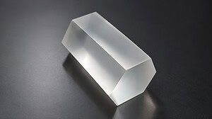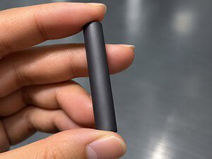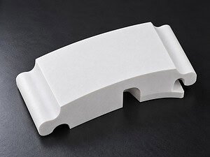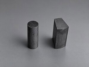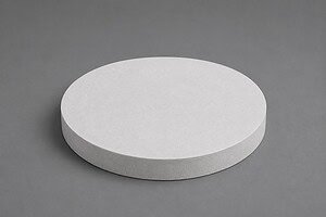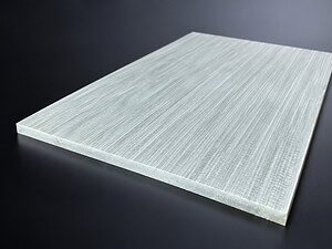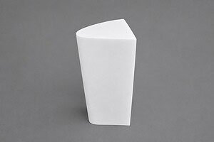
Keramikschneiden mit Diamantdraht wird verwendet, wenn ein hartes, sprödes Werkstück mit kontrollierter Schnittkraft und begrenztem Materialverlust getrennt werden muss. Das Verfahren kann für Aluminiumoxid, Zirkonoxid, Siliziumkarbid und andere technische Keramiken geeignet sein, aber diese Materialien verhalten sich nicht identisch. Die Kornstruktur, Bruchzähigkeit, Porosität, Teilegeometrie und der erforderliche Kantenbeschaffenheit beeinflussen das Ergebnis.
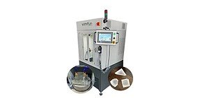
Dieser Leitfaden konzentriert sich auf die Prozessplanung und nicht auf die Förderung eines Maschinenmodells. Für Ausrüstungsoptionen und Anwendungsunterstützung siehe die Hauptseite Keramikschneidlösungen.
Warum technische Keramiken schwer zu schneiden sind
Technische Keramiken kombinieren hohe Härte mit geringer Toleranz gegenüber Zugspannung. Eine Schneidmethode kann Material erfolgreich entfernen und dennoch Kantenabsplitterungen, Untergrundrisse, lokale Erwärmung oder eine unannehmbare Schnittfuge erzeugen. Dünne Wände, Ringe, Rohre und gesinterte Teile mit innerer Spannung erfordern eine besonders sorgfältige Unterstützung.
- Absplitterung: entwickelt sich oft dort, wo der Draht eine ungestützte Kante ein- oder austritt.
- Rissbildung: kann durch innere Defekte, Spannungsbelastung, thermische Gradienten oder übermäßige Vorschubgeschwindigkeit ausgelöst werden.
- Drahtwanderung oder -biegung: kann auftreten, wenn Vorschub, Spannung, Ausrichtung und Schnitttiefe nicht ausgewogen sind.
- Materialverlust: hängt vom Draht und der Schleifmittelumgebung, dem Rundlauf und der Prozessstabilität ab, nicht allein vom Drahtdurchmesser.
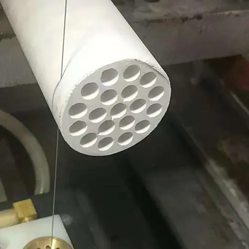
Schneiden von Aluminiumoxid, Zirkonoxid und Siliziumkarbid
Der Materialname ist nur der Ausgangspunkt. Güte, Dichte, Zusatzstoffe, Sinterzustand und Geometrie können das Schneidverhalten verändern. Der folgende Vergleich identifiziert die Fragen, die vor einem Probeschnitt geprüft werden sollten; er ersetzt keine Mustervalidierung.
| Material | Typische Schnittprobleme | Prozessaufmerksamkeit | Zu bestätigende Informationen |
|---|---|---|---|
| Aluminiumoxid | Kantenabsplitterung, Sprödbruch und Oberflächenschäden | Stabile Unterstützung, kontrollierter Ein- und Austritt, Kühlmittelzufuhr und konservative Vorschubentwicklung | Reinheit, Sinterzustand, Wandstärke, Kantenanforderung und zulässige Schnittfuge |
| Zirkoniumdioxid | Güteabhängige Zähigkeit, lokale Spannung und Nachbearbeitungszugabe | Vermeiden Sie abrupte Belastung; überprüfen Sie den Spannungsdruck der Vorrichtung, den Drahtzustand und die thermische Kontrolle | Stabilisierte Güte, Dichte, Teilegeometrie, Toleranz und nachgeschaltetes Schleifen |
| Siliziumkarbid | Hohe Härte, abrasiver Verschleiß und Bruch an ungestützten Merkmalen | Überprüfen Sie den Zustand des Schleifmittels, die Ausrichtung, die Späneentfernung und die Werkstückunterstützung | SiC-Typ, Porosität, Schnitttiefe, Kühlmittelzulassung und Zieloberfläche |
Geometriespezifische Beispiele finden Sie unter Aluminiumoxid-Keramikringschneiden und silicon carbide ring cutting. Diese Seiten zeigen, warum Ringwände, Bohrungsunterstützung und Schnittrichtung eine separate Planung verdienen.
Wie Diamantdraht Keramik entfernt
Ein diamantbeschichteter Draht entfernt Keramik durch wiederholte Schleifmittelkontakte und nicht durch eine einzelne Schneide. Eine Endlosschleife durchläuft die Schnittzone, während die Maschine die Drahtbewegung, Spannung, Vorschub und Werkstückposition steuert. Die geringere Schleifmittelwirkung kann die Belastung spröder Teile reduzieren, aber sie eliminiert nicht die Notwendigkeit einer korrekten Vorrichtung und Späneentfernung.
Die Drahtspezifikation sollte auf die Keramik und die Prozessbeschränkung abgestimmt sein. Durchmesser und Schleifmittelgröße beeinflussen die Schnittumgebung, während die Beschichtungsstruktur den Schleifmittelkontakt und den Spanraum beeinflusst. Drahtstrukturen auf Produktebene und Beschichtungsoptionen werden auf der Seite Seite mit Spezifikationen für Diamantdraht.
Prozesskontrollen für Absplitterungen, Risse und Schnittfugen
| Kontrollbereich | Warum es wichtig ist | Warnsignale | Praktische Reaktion |
|---|---|---|---|
| Vorrichtung und Unterstützung | Verhindert Bewegung und begrenzt Zugspannung nahe dem Schnitt | Ausbruch an der Austrittskante, Vibration oder Verschiebung des Teils | Unterstützen Sie empfindliche Kanten und verteilen Sie die Klemmkraft, ohne das Teil zu verzerren |
| Vorschubgeschwindigkeit | Legt die Eingriffslast auf den Schleifdraht fest | Absplitterung, Biegung, Überlastung oder instabiles Geräusch | Entwickeln Sie den Vorschub schrittweise aus einem repräsentativen Teststück |
| Drahtspannung | Hält einen stabilen Schnittweg aufrecht | Wanderung bei niedrig; übermäßige Draht- oder Lagerbelastung bei hoch | Verwenden Sie den sicheren Bereich des Maschinen- und Drahtlieferanten und überprüfen Sie dann die Geradheit des Schnitts |
| Kühlmittel und Späneentfernung | Kontrolliert Wärme, spült Partikel aus und begrenzt die Belastung | Schmutziger Schnitt, Temperaturanstieg oder sich veränderndes Entfernungsverhalten | Bestätigen Sie die Kühlmittelkompatibilität, Richtung, Filtration und Reinigungsanforderungen |
| Ein- und Ausstiegsstrategie | Kontrolliert Spannungen an exponierten Kanten | Lokalisierte Abplatzungen am Anfang oder Ende des Schnitts | Verbessern Sie die Rückseitenunterstützung und reduzieren Sie abrupte Eingriffe in der Nähe von empfindlichen Kanten |
| Drahtzustand und Ausrichtung | Beeinflusst Schnittspaltkonsistenz und Oberflächenbeschaffenheit | Periodische Markierungen, Verjüngung oder erhöhte Zykluszeit | Überprüfen Sie Drahtverschleiß, Führungsräder, Rundlauf und Schnittwegausrichtung |
Fragen zu Nass-, Trocken- und Kryoschnitten
Wasser oder ein kompatibles Kühlmittel wird häufig für technische Keramiken bewertet, da es Schmutz wegtragen und die Temperatur moderieren kann. Trockenschnitte können erforderlich sein, wenn das Werkstück, der nachgeschaltete Prozess oder Kontaminationsregeln Flüssigkeiten verbieten. In diesem Fall werden Drahtbeschichtung, Staubabsaugung und Vorschubentwicklung wichtiger.
Suchen nach kryogenem Diamantdrahtsägen von Keramiken beschreiben ein spezialisiertes Forschungs- oder Prozessentwicklungsthema, nicht eine universelle Produktionsumgebung. Kühlmedien, Risiko von thermischen Schocks, Verhalten der Spannvorrichtung und Materialreaktion müssen zusammen validiert werden. Eine Standardseite für Keramikschneiden sollte keine kryogene Leistung beanspruchen, ohne Testnachweise für die spezifische Güte und Geometrie.
Video zur Anwendung von Keramikschneiden
Das beigefügte Video demonstriert eine Anwendung zum Schneiden von Keramik. Es sollte als Prozessnachweis für dieses Muster behandelt werden, nicht als universelle Parameterempfehlung. Vergleichen Sie das Material, die Abmessungen, die Unterstützung und die Akzeptanzkriterien des Musters mit dem beabsichtigten Produktionsbauteil.
Informationen, die vor einem Keramik-Testschnitt benötigt werden
| Artikel | Was zu liefern ist | Warum es den Prozess beeinflusst |
|---|---|---|
| Material | Keramikfamilie, genaue Güte, Dichte, gesinterter oder grüner Zustand | Ändert Härte, Bruchverhalten, Verschleiß und Kühlmittelverträglichkeit |
| Workpiece | Länge, Breite, Dicke, Bohrung, Wandstärke und verfügbare Klemmfläche | Bestimmt Unterstützung, Verfahrweg, Schnitttiefe und Spannvorrichtungsdesign |
| Schnittgeometrie | Gerade, Ring, Rohr, Block, Kontur, Ein- und Ausstiegsorte | Definiert Drahtweg und anfällige Kanten |
| Qualitätsziel | Toleranz, Schnittspaltzugabe, Abplatzgrenze, Ebenheit und Oberflächenanforderung | Legt die Akzeptanzkriterien für die Prozessentwicklung fest |
| Prozessbeschränkung | Nass- oder Trockenanforderung, zugelassenes Kühlmittel, Kontaminations- und Reinigungsgrenzen | Leitet Drahtstruktur und Schmutzkontrollmethode |
| Produktionsziel | Menge, Zykluszeiterwartung und nachgeschaltete Endbearbeitung | Balanciert Schnittqualität, Drahtlebensdauer und Durchsatz |
Häufig gestellte Fragen
Können die gleichen Einstellungen für Aluminiumoxid, Zirkoniumdioxid und Siliziumkarbid verwendet werden?
Nein. Ihre Härte, Zähigkeit, Mikrostruktur und ihr Verschleißverhalten unterscheiden sich. Selbst zwei Güten innerhalb derselben Keramikfamilie können unterschiedliche Vorschub-, Stütz-, Kühlmittel- und Drahtwahl erfordern.
Wie können Kantenabplatzungen reduziert werden?
Beginnen Sie mit der Überprüfung der Spannvorrichtungsunterstützung, der Ein- und Ausstiegsbereiche, der Vorschubgeschwindigkeit, des Drahtzustands und der Ausrichtung. Abplatzungen sind normalerweise ein symptomatisches Problem des Gesamtsystems und keine einzelne Einstellung, die geändert werden muss.
Erzeugt ein dünnerer Diamantdraht immer einen kleineren Schnittspalt?
Nicht immer. Die Schleifhülle, die Konsistenz der Beschichtung, der Drahtrundlauf, die Spannung, der Vorschub, die Schnitttiefe und Vibrationen beeinflussen auch den tatsächlichen Schnittspalt.
Ist Kühlmittel für das Schneiden von Keramik erforderlich?
Kühlmittel ist üblicherweise nützlich zur Wärme- und Schmutzkontrolle, aber einige Anwendungen erfordern eine Trockenbearbeitung. Bestätigen Sie die Materialverträglichkeit, die Kontaminationsregeln und die Reinigungsanforderungen, bevor Sie die Methode wählen.
Was sollte bei einem Testschnitt gemessen werden?
Messen Sie Schnittspalt, Kantenabplatzungen, Geradheit oder Ebenheit, Oberflächenbeschaffenheit und Zykluszeit. Zeichnen Sie auch Drahtverschleiß, Kühlmittel- oder Staubverhalten, Spannvorrichtungsspuren und eventuell nach der Reinigung auftretende Risse auf.
Abschluss
Zuverlässiges Keramikschneiden mit Diamantdraht beginnt mit der genauen Materialgüte und Teilegeometrie. Aluminiumoxid, Zirkoniumdioxid und Siliziumkarbid erfordern unterschiedliche Aufmerksamkeit für Bruch, Verschleiß, Kühlmittel, Unterstützung und Vorschub. Anstatt einen generischen Parametersatz zu kopieren, definieren Sie die Akzeptanzkriterien, führen Sie einen repräsentativen Test durch und passen Sie das Draht-Maschine-Spannvorrichtungssystem anhand der gemessenen Ergebnisse an.