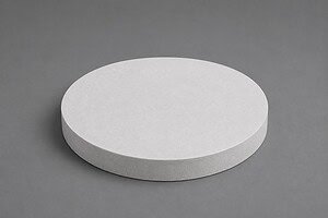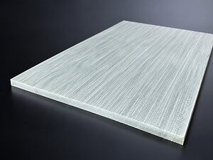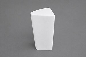
El corte cerámico con hilo de diamante se utiliza cuando una pieza de trabajo dura y quebradiza debe separarse con una fuerza de corte controlada y una pérdida de material limitada. El proceso puede ser adecuado para alúmina, zirconia, carburo de silicio y otras cerámicas técnicas, pero estos materiales no se comportan de manera idéntica. La estructura del grano, la tenacidad a la fractura, la porosidad, la geometría de la pieza y el estado del borde requerido influyen en el resultado.
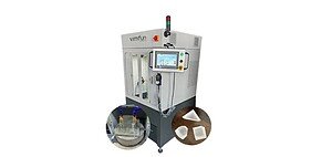
Esta guía se centra en la planificación del proceso en lugar de promocionar un modelo de máquina. Para opciones de equipo y soporte de aplicaciones, consulte la página principal de solución de corte cerámico.
Por qué las cerámicas técnicas son difíciles de cortar
Las cerámicas técnicas combinan alta dureza con baja tolerancia al estrés de tracción. Un método de corte puede eliminar material con éxito y, aun así, crear astillas en los bordes, grietas subsuperficiales, calentamiento local o un corte inaceptable. Las paredes delgadas, los anillos, los tubos y las piezas sinterizadas con estrés interno requieren un soporte especialmente cuidadoso.
- Desportillado: a menudo se desarrolla donde el hilo entra o sale de un borde sin soporte.
- Agrietamiento: puede ser provocado por defectos internos, estrés de sujeción, gradientes térmicos o alimentación excesiva.
- Desviación o arqueo del hilo: puede aparecer cuando la alimentación, la tensión, la alineación y la profundidad de corte no están equilibradas.
- Pérdida de material: depende de la envoltura del hilo y el abrasivo, la excentricidad y la estabilidad del proceso, no solo del diámetro del hilo.
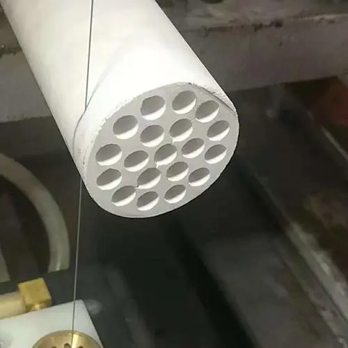
Corte de alúmina, zirconia y carburo de silicio
El nombre del material es solo el punto de partida. El grado, la densidad, los aditivos, el estado de sinterización y la geometría pueden cambiar el comportamiento de corte. La comparación a continuación identifica las preguntas que deben verificarse antes de un corte de prueba; no sustituye la validación de muestras.
| Material | Preocupación típica de corte | Atención al proceso | Información a confirmar |
|---|---|---|---|
| Alúmina | Astillado del borde, fractura frágil y daño superficial | Soporte estable, entrada y salida controladas, suministro de refrigerante y desarrollo de alimentación conservadora | Pureza, estado sinterizado, espesor de pared, requisito de borde y corte admisible |
| Zirconia | Tenacidad dependiente del grado, estrés local y margen de acabado | Evite la carga abrupta; verifique la presión del dispositivo de sujeción, el estado del hilo y el control térmico | Grado estabilizado, densidad, geometría de la pieza, tolerancia y rectificado posterior |
| Carburo de silicio | Alta dureza, desgaste abrasivo y fractura en características sin soporte | Verifique el estado del abrasivo, la alineación, la eliminación de desechos y el soporte de la pieza de trabajo | Tipo de SiC, porosidad, profundidad de sección, permiso de refrigerante y superficie objetivo |
Para ejemplos específicos de geometría, revise corte de anillos de cerámica de alúmina y corte de anillos de carburo de silicio. Estas páginas muestran por qué las paredes de los anillos, el soporte del orificio y la dirección de corte merecen una planificación separada.
Cómo el hilo de diamante elimina la cerámica
Un hilo recubierto de diamante elimina la cerámica mediante contactos abrasivos repetidos en lugar de un único filo de corte. Un bucle continuo viaja a través de la zona de corte mientras la máquina controla el movimiento del hilo, la tensión, la alimentación y la posición de la pieza de trabajo. La acción abrasiva de baja fuerza puede reducir el impacto en piezas quebradizas, pero no elimina la necesidad de una sujeción correcta y control de desechos.
La especificación del hilo debe coincidir con la cerámica y la restricción del proceso. El diámetro y el tamaño del abrasivo influyen en la zona de corte, mientras que la estructura del recubrimiento afecta el contacto abrasivo y el espacio para virutas. Las estructuras de hilo a nivel de producto y las opciones de recubrimiento se describen en la página de especificación del hilo de diamante.
Controles de proceso para astillado, grietas y corte
| Área de control | Por qué importa | Señales de advertencia | Respuesta práctica |
|---|---|---|---|
| Dispositivo de sujeción y soporte | Previene el movimiento y limita el estrés de tracción cerca del corte | Rotura del borde de salida, vibración o desplazamiento de la pieza | Soporte para bordes frágiles y distribución de la carga de sujeción sin distorsionar la pieza |
| Velocidad de avance | Establece la carga de compromiso en el hilo abrasivo | Astillado, arqueo, sobrecarga o sonido inestable | Desarrolle la alimentación gradualmente a partir de una pieza de prueba representativa |
| Tensión del cable | Mantiene una trayectoria de corte estable | Desviación cuando es baja; carga excesiva del hilo o del rodamiento cuando es alta | Utilice el rango seguro del proveedor de la máquina y del hilo, luego verifique la rectitud del corte |
| Refrigerante y eliminación de desechos | Controla el calor, arrastra partículas y limita la carga | Corte sucio, aumento de temperatura o cambio en el comportamiento de remoción | Confirmar compatibilidad del refrigerante, dirección, filtración y requisitos de limpieza |
| Estrategia de entrada y salida | Controles de estrés en los bordes expuestos | Virutas localizadas al inicio o al final del corte | Mejorar el soporte de respaldo y reducir el compromiso abrupto cerca de los bordes frágiles |
| Condición y alineación del alambre | Afecta la consistencia de la ranura y la condición de la superficie | Marcas periódicas, conicidad o aumento del tiempo de ciclo | Inspeccionar el desgaste del alambre, las ruedas guía, la oscilación y la alineación de la trayectoria de corte |
Preguntas sobre corte húmedo, seco y criogénico
El agua o un refrigerante compatible se evalúa comúnmente para cerámicas técnicas porque puede eliminar los escombros y moderar la temperatura. El corte en seco puede ser necesario cuando la pieza de trabajo, el proceso posterior o las reglas de contaminación prohíben el líquido. En ese caso, el recubrimiento del alambre, la extracción de polvo y el desarrollo de la alimentación se vuelven más importantes.
Las búsquedas de corte por alambre de diamante criogénico de cerámicas describen un tema especializado de investigación o desarrollo de procesos, no un entorno de producción universal. Los medios de enfriamiento, el riesgo de choque térmico, el comportamiento del accesorio y la respuesta del material deben validarse juntos. Una página estándar de corte de cerámica no debe reclamar un rendimiento criogénico sin evidencia de prueba del grado y geometría específicos.
Video de aplicación de corte de cerámica
El video retenido demuestra una aplicación de corte de cerámica. Debe tratarse como evidencia del proceso para esa muestra, no como una recomendación de parámetros universal. Compare el material, las dimensiones, el soporte y los criterios de aceptación de la muestra con la pieza de producción prevista.
Información requerida antes de un corte de prueba de cerámica
| Artículo | Qué proporcionar | Por qué afecta el proceso |
|---|---|---|
| Material | Familia de cerámica, grado exacto, densidad, estado sinterizado o verde | Cambia la dureza, el comportamiento de fractura, el desgaste y la compatibilidad del refrigerante |
| Pieza de Trabajo | Longitud, ancho, espesor, diámetro interior, pared y área de sujeción disponible | Determina el soporte, el recorrido, la profundidad de corte y el diseño del accesorio |
| Geometría de corte | Recto, anillo, tubo, bloque, contorno, ubicaciones de entrada y salida | Define la trayectoria del alambre y los bordes vulnerables |
| Objetivo de calidad | Tolerancia, margen de ranura, límite de astillado, planitud y requisito de superficie | Establece los criterios de aceptación para el desarrollo del proceso |
| Restricción del proceso | Requisito húmedo o seco, refrigerante permitido, límites de contaminación y limpieza | Guía la estructura del alambre y el método de control de escombros |
| Objetivo de producción | Cantidad, expectativa de tiempo de ciclo y acabado posterior | Equilibra la calidad del corte, la vida útil del alambre y el rendimiento |
Preguntas frecuentes
¿Se pueden usar las mismas configuraciones para alúmina, zirconia y carburo de silicio?
No. Su dureza, tenacidad, microestructura y comportamiento de desgaste difieren. Incluso dos grados dentro de la misma familia de cerámica pueden requerir diferentes opciones de alimentación, soporte, refrigerante y alambre.
¿Cómo se puede reducir el astillado del borde?
Comience por verificar el soporte del accesorio, los bordes de entrada y salida, la velocidad de alimentación, la condición y la alineación del alambre. El astillado suele ser un síntoma a nivel del sistema en lugar de un problema que se resuelve cambiando solo una configuración.
¿Un alambre de diamante más delgado siempre produce una ranura más pequeña?
No siempre. El sobre de abrasivo, la consistencia del recubrimiento, la oscilación del alambre, la tensión, la alimentación, la profundidad de corte y la vibración también influyen en la ranura real.
¿Se requiere refrigerante para el corte de cerámica?
El refrigerante es comúnmente útil para el control de calor y escombros, pero algunas aplicaciones requieren procesamiento en seco. Confirme la compatibilidad del material, las reglas de contaminación y los requisitos de limpieza antes de elegir el método.
¿Qué se debe medir en un corte de prueba?
Mida la ranura, el astillado del borde, la rectitud o la planitud, la condición de la superficie y el tiempo de ciclo. Registre también el desgaste del alambre, el comportamiento del refrigerante o del polvo, las marcas del accesorio y cualquier grieta que aparezca después de la limpieza.
Conclusión
El corte confiable de cerámica con alambre de diamante comienza con el grado exacto del material y la geometría de la pieza. La alúmina, la zirconia y el carburo de silicio requieren una atención diferente a la fractura, el desgaste, el refrigerante, el soporte y la alimentación. En lugar de copiar un conjunto de parámetros genérico, defina los criterios de aceptación, ejecute una prueba representativa y ajuste el sistema de alambre-máquina-accesorio a partir de los resultados medidos.