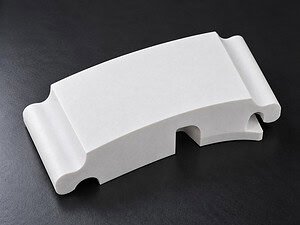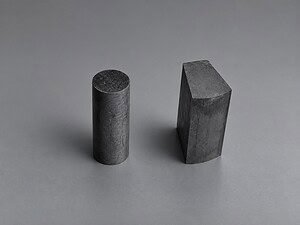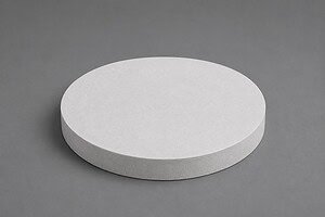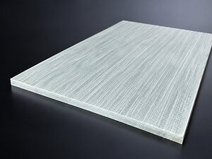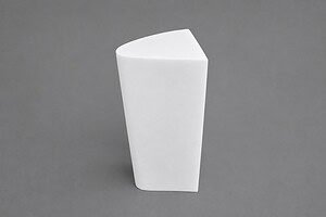
The request came with a drawing attached: a 200 mm × 100 mm × 50 mm mullite block that needed a curved profile milled through its full 50 mm thickness, with a minimum radius of 0.5 mm at the tightest transition. The customer had already tried rotary diamond grinding — the 0.5 mm radius was simply too tight for any grinding wheel to track, and EDM wasn’t an option on a non-conductive ceramic. They needed something that could follow a contour at that scale without shattering the part.
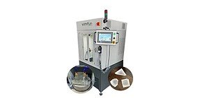
We ran this on a VIMFUN SVI series endless diamond wire saw using a 0.65 mm wire at 35 m/s. The result: a smooth, continuous curved surface with clean radius transitions, flat cut faces, and no visible edge chipping along any of the profile edges. This case documents what it took to get there.
The Application — Custom Mullite Profile for High-Temperature Use
Mullite (3Al₂O₃·2SiO₂) sits at the harder end of the oxide ceramics family. Its melting point approaches 1830 °C, and it holds structural integrity in environments that would cause most refractories to creep or react. These properties make it a consistent choice for kiln furniture, semiconductor thermal processing fixtures, and high-temperature industrial components where dimensional stability under prolonged heat cycling actually matters.
The demand for shaped mullite pieces — rather than flat tiles or simple rods — has grown as engineers push component geometry to reduce weight, optimize heat flow paths, and create interference-fit interfaces that don’t need secondary adhesive. A flat mullite brick is easy enough to produce by pressing and sintering. A custom-profiled part with sub-millimeter radius features is a different problem.
Standard cutting approaches for seramik kesimi struggle here. Rotary diamond wheels can approximate curves, but they can’t reach radii tighter than the wheel’s own edge radius. Wire EDM achieves fine radii but cannot be used on electrically non-conductive materials like mullite. Inner-diameter sawing produces straight cuts only. The geometry of this part eliminated all three options before we even looked at parameters.
The Challenge — Mullite Profile Cutting at 50 mm Depth
Mullite sits at Mohs hardness 6–7, which is abrasable but not soft. The more important characteristic for cutting is its low fracture toughness. Mullite doesn’t deform plastically before it breaks — it propagates cracks. Any lateral force on the workpiece during cutting, or any sudden direction change that loads the material edge-on, risks chipping the cut surface or, worse, fracturing the part entirely.
Three constraints stacked on top of each other made this mullite profile cutting case genuinely demanding:
1. The 50 mm thickness. In contour cutting, the wire traces a path through the material while the workpiece feeds into it. Over a 50 mm depth, any deflection of the wire — however small — compounds into a geometry error at the bottom of the cut. If the wire bows under cutting force, the bottom profile won’t match the top. Getting both faces to agree requires keeping wire deflection small throughout the full depth.
2. The 0.5 mm minimum radius. At tight radii, the workpiece must change direction relative to the wire quickly. If the feed rate at that moment is too high, the wire gets pushed sideways before the geometry can correct, and the resulting corner is either rounded too much or chipped. The wire doesn’t “know” it’s approaching a tight transition — the motion control has to slow it down proactively.
3. The wire exit geometry. Where the wire exits the material at the end of each profile pass, the ceramic edge is momentarily unsupported on one side. This is where önceden sinterlenmiş alümina seramik kesimi has the same failure mode: exit-side chipping. Brittle ceramics chip preferentially at the exit point if the feed rate isn’t reduced before the wire breaks through.
None of these challenges is individually unusual. Having all three on the same part, in a ceramic that fractures rather than bends, is what made this a process development problem rather than a setup problem.
Mullite Profile Cutting Setup on the VIMFUN SVI Wire Saw
The VIMFUN SVI series handles contour cutting through CNC-coordinated XY motion — the workpiece moves in two axes simultaneously while the wire runs at constant speed. Contour geometry is uploaded as a path file; the machine interpolates the profile rather than approximating it as a series of straight segments. This matters for smooth radius transitions: a true arc, not a polygon with very short sides.
| Parametre | VIMFUN SVI | Notlar |
|---|---|---|
| Makine | VIMFUN SVI (contour cutting) | Endless diamond wire, CNC path interpolation |
| Tel çapı | 65 mm | Diamond-coated, continuous loop — no weld joints |
| Tel hızı | Sonsuz (kapalı döngü) elmas tel döngüsü | Constant throughout the cut |
| İlerleme hızı | Reduced at 0.5 mm radius and wire exit | Standard rate on straight/large-radius sections |
| Tel gerginliği | Stable closed-loop control | Maintained throughout depth and direction changes |
| Workpiece clamping | Rigid fixture | Prevents vibration-induced chipping |
| Soğutucu | Water-based, continuous flood | Applied at wire–workpiece contact zone |
The 0.65 mm wire was selected because it physically fits the 0.5 mm minimum radius — the wire diameter needs to be no larger than the radius being cut, otherwise the wire geometry itself prevents the feature from forming. A 1.0 mm wire would have been faster on the straight sections but geometrically incapable of producing the 0.5 mm transition. This is a firm constraint, not a preference.
Feed rate management at the tight radius. On straight runs and large-radius curves, the feed rate runs at the standard process setting for this wire diameter and material. As the path approaches the 0.5 mm radius zone, the CNC slows the feed. The slower feed keeps cutting force low while the direction is changing rapidly, which prevents the wire from deflecting away from the programmed path. Once the wire has cleared the tight zone, feed rate ramps back up. This is the same principle used in silisyum karbür halka kesimi when cutting narrow slots at sharp corners — the geometry controls the speed, not the operator.
Wire exit strategy. On this profile, every pass ends with the wire exiting through a ceramic edge. The SVI reduced feed rate again as the wire approached the exit face — a brief but critical deceleration that left the edge intact. Skipping this step typically produces the classic “exit chip”: a small fragment breaks free from the exit face where the unsupported ceramic surface encounters the full cutting force.
Clamping. Mullite at this size (200 × 100 × 50 mm) is heavy enough to sit stably but light enough to rock under vibration if poorly clamped. A rigid fixture was used to eliminate any workpiece movement during cutting. Any micro-movement at the workpiece translates directly into surface roughness or, at the 0.5 mm radius, a chipped corner.
The relationship between Tel hızı, gerginliği ve ilerleme hızı in contour cutting is more coupled than in straight cutting. In straight cuts, you can often optimize these variables independently. In contour cutting, a direction change that loads the wire sideways effectively raises the cutting resistance — so the same feed rate that works on a straight run can cause deflection at a sharp turn.
Results — Mullite Profile Cutting Geometry and Surface Quality
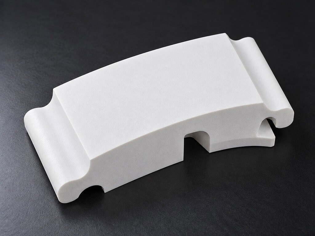
The cut profile matched the drawing. Smooth curve through the contoured sections, clean 0.5 mm radius at the tightest transition, flat cut surface along the full 50 mm depth. No visible edge chipping on entry faces, profile edges, or exit faces.
Specifically:
- Curve continuity: The surface curved without any visible faceting or step discontinuity between CNC interpolation segments.
- Radius transition: The 0.5 mm radius was preserved — the wire geometry and the reduced-feed strategy held the corner.
- Top-to-bottom consistency: No measurable divergence between the profile at the top face and the profile at the bottom face. Wire deflection was controlled well enough to keep both faces aligned.
- Yüzey durumu: Flat cut surface with the characteristic texture of diamond wire cutting — no glazing, no heat damage, no signs of subsurface cracking at the profile edges.
A comparison worth noting: rotary diamond grinding on the same profile would require multiple passes with progressively smaller tools, and the 0.5 mm radius would still be at the edge of feasibility for even the finest grinding bits. Total machining time would be longer, and each tool change introduces a new geometric reference that must be re-registered. The wire saw runs the full profile as a continuous path, single setup, without tool changes.
One honest limitation: contour cutting on this type of part is slower than straight-through slicing. The feed rate reductions at tight radii and exit points add time, and cutting force management through direction changes requires conservative feed settings on the curved sections. If a customer has a simple rectangular slab cut, a straight-cutting setup will always be faster. The advantage of the SVI’s contour capability is geometric access, not speed.
For reference on how elmas tel testere seramik kesme doğruluğu scales with wire diameter and radius constraints: radii tighter than 0.5 mm are achievable but require switching to finer wire (e.g., 0.35 mm or smaller), which reduces cutting speed further and increases wire cost. The 0.65 mm wire at 0.5 mm minimum radius is near the limit of what this diameter can handle geometrically.

Send Us Your Mullite Drawing
If you’re working with a mullite component that requires a curved profile, irregular cross-section, or features that grinding or EDM can’t produce, this process applies directly.
To give you a parameters estimate and feasibility assessment, send us:
- Workpiece dimensions (length × width × thickness)
- Material specification — fired mullite, fused mullite, or another composition
- Profile drawing or DXF file showing the required contour
- Minimum radius on the drawing
- Surface finish requirement (as-cut acceptable, or do you need secondary lapping?)
- Quantity: single sample, small batch, or production volume
We’ll review the geometry, confirm wire diameter compatibility with your smallest radius, and advise on expected cycle time and dimensional tolerance before you commit to anything.
İletişim: daria@endlesswiresaw.com
SSS
Q: Can the VIMFUN SVI cut mullite profiles with radii smaller than 0.5 mm?
Smaller radii are geometrically achievable, but require finer wire. The SVI’s 0.65 mm wire cannot produce radii tighter than approximately 0.5 mm — the wire itself is the limiting dimension. For radii in the 0.2–0.4 mm range, we would switch to a 0.35 mm or 0.25 mm wire, which extends cycle time and changes the cutting parameters. Send us the drawing and we’ll confirm feasibility for your specific geometry.
Q: What surface finish does the VIMFUN SVI produce on mullite?
The as-cut surface on this part was flat with no observable edge chipping, consistent with the results we see on other dense oxide ceramics. Diamond wire cutting on mullite produces a matte finish — rougher than a lapped surface, but without the subsurface damage that grinding can introduce at sharp features. If you need a tighter Ra for sealing faces or optical interfaces, lapping after wire cutting is the standard follow-on step.
Q: How does mullite profile cutting compare to cutting other hard ceramics like alumina or silicon carbide?
Mullite’s hardness (Mohs 6–7) is lower than alumina (~9) and silicon carbide (~9.5), so wire wear is lower and feed rates can be slightly higher on equivalent geometry. The more important variable for mullite is its fracture toughness — mullite is somewhat more susceptible to exit chipping than high-density alumina at equivalent thickness. The feed reduction strategy at exit points is the same approach we use for alumina and SiC, just calibrated to mullite’s specific crack propagation behavior.
About VIMFUN
VIMFUN specializes in endless diamond wire cutting for advanced ceramics, graphite, optical glass, quartz, composites, and other hard and brittle materials. The SVI series handles contour and profile cutting with CNC path interpolation; the SH60-60 handles straight and multi-wire slicing. Learn more at https://www.endlesswiresaw.com.
About the Author
Written by the VIMFUN Applications Engineering Team — specialists in precision cutting process development for advanced materials across ceramics, composites, and hard-to-machine workpieces.