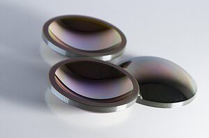
We had a cutting line producing 300μm silicon wafers with ±25μm TTV — three times the spec limit. The operator swore the wire was defective. Static bench testing showed the tension was “fine.” But under operating load at 50 m/s, dynamic tension distribution was varying by 7% around the loop. The wire wasn’t defective. It was wandering laterally at the cutting zone because of tension non-uniformity that only showed up when the loop was actually running.
This is the pattern we see over and over. Tension problems hide from static inspection, then show up as TTV failures, premature wire breakage, or patchy wear that gets blamed on plating quality. Understanding tension distribution — how it varies around the loop, how it accumulates fatigue damage over time, and where machine-side issues creep in — is the difference between a cutting line that hits spec and one that generates mysterious quality complaints.
This article covers the physics of tension in closed-loop Diamantdrahtschleifen, the three failure modes that poor tension distribution causes, and how we test and control it in production.

Why Tension Distribution Matters for Loop Performance
A diamond wire loop running at 40-85 m/s isn’t a rigid tool — it’s a flexible steel cable under dynamic load. Tension is what makes it behave like a rigid tool in the cutting zone. Without uniform tension, the wire doesn’t track straight; it oscillates laterally, and every oscillation translates into surface finish problems on the workpiece.
The guitar string analogy gets it right. A guitar string at uniform tension vibrates in clean, predictable modes. Apply uneven tension — pinch it harder on one side — and the vibration pattern becomes chaotic. Diamond wire loops behave the same way. Uniform tension means the wire maintains a single stable cutting plane. Non-uniform tension means the wire wobbles, the kerf wanders, and your total thickness variation (TTV) goes out of spec.
On paper, tension looks like one of the simpler parameters: set the tensioner to 150N, done. In practice, tension distribution around the loop is the single most common root cause of “unexplained” surface finish problems we’ve investigated. The setpoint is easy; maintaining uniform distribution under dynamic load is hard.
How Tension Variation Causes Cutting Failures
Poor tension distribution shows up as three distinct failure modes. They’re easy to diagnose once you know what to look for, but most operators misattribute them to wire quality or machine wear.
Wire wander (snaking)
The wire bows laterally under cutting load, producing wavy cuts. On Silizium-Wafer slicing, this shows up as TTV exceeding spec — the wafers are thicker on one side than the other. On thicker workpieces, you’ll see visible waviness in the cut surface, sometimes with a periodic pattern that matches the loop circumference.
The 300μm wafer example from the opening is typical. At 7% dynamic tension variance, the wire was bowing roughly 20-30 microns off its intended path under load. That’s enough to push the wafers out of ±12μm TTV spec, even though every other parameter on the machine was within normal range. Fixing the tensioner calibration brought variance under 2% and TTV back to ±8μm immediately.
Premature breakage at consistent intervals
If your wires break at roughly the same hour mark — 50 hours, 80 hours, whatever — that’s fatigue at a stress concentration point, not normal wear. Localized tension spikes during each revolution exceed the wire’s fatigue limit at a specific location. Damage accumulates with every pass until the wire snaps.
Das verräterische Zeichen ist die Konsistenz. Normaler Verschleiß erzeugt eine Verteilung von Ausfallzeiten; Ermüdung an einer Spannungskonzentration erzeugt eine enge Gruppierung. Wir haben Chargen von Draht gesehen, die auf derselben Maschine 48-52 Stunden Ausfälle zeigten, während eine identische Drahtcharge auf einer anderen Maschine 150+ Stunden lief. Das ist kein Drahtproblem.
Flickiger Verschleiß
Einige Abschnitte der Schleife schleifen statt zu schneiden. Sie sehen glänzende blanke Metallstellen, wo die Nickelbeschichtung durchgetragen wurde, abwechselnd mit noch beschichteten Abschnitten. Bediener bezeichnen dies oft als “Problem mit der Beschichtungsqualität” – das ist es nicht. Eine gleichmäßige Beschichtung verschleißt nicht ungleichmäßig, es sei denn, die Schneidlast ist ungleichmäßig um die Schleife verteilt.
Die Ursache ist fast immer eine Spannungsänderung. Abschnitte mit höherer lokaler Spannung werden stärker in das Werkstück gepresst; Abschnitte mit geringerer Spannung gleiten darüber hinweg, ohne richtig zu schneiden. Der Abrieb an den überlasteten Abschnitten wird schnell abgetragen, während die unterlasteten Abschnitte beschichtet, aber unproduktiv bleiben.
Wie die Zahlen aussehen
Hier sehen Sie, wie eine gute und eine schlechte Spannungsverteilung bei den wichtigsten Kennzahlen aussehen:
| Metrisch | Gut kontrollierte Schleife | Schlecht kontrollierte Schleife | Warum es wichtig ist |
|---|---|---|---|
| Dynamische Spannungsabweichung | < 2% | 5-10% | Über 3% verursacht sichtbares Drahtwandern |
| Vibrationsamplitude in der Schnittzone | < 0,05 mm | > 0,15 mm | Korreliert direkt mit dem Schnittfugen-Nachführfehler |
| Zugversagensrate | < 0,1% pro 100 Stunden | > 2,01 TP5T pro 100 Stunden | Jede Unterbrechung bedeutet 30-60 Minuten Ausfallzeit + potenziellen Werkstückverlust |
| TTV auf 300μm Wafern | ±8μm | ±25μm+ | 7% Spannungsabweichung war in unserem Fall die Ursache |
Statische vs. dynamische Spannungsmessung: Warum sie wichtig ist
Hier verbergen sich die meisten Spannungsprobleme. Statische Bandmessung – das Ziehen des Drahtes mit einem hängenden Gewicht oder einer Federwaage im Stillstand – erfasst nicht das dynamische Verhalten, das tatsächlich beim Schneiden eine Rolle spielt.
Wenn eine Schlaufe stillsteht, verteilt sich die Spannung gleichmäßig über den Weg. Beginnen Sie sie mit 50 m/s zu bewegen, und drei Dinge ändern sich: Zentripetalkräfte an den Riemenscheiben fügen dynamische Komponenten hinzu, jede Masse- oder Steifigkeitsungleichmäßigkeit in der Schlaufe erzeugt periodische Spannungsimpulse, und die Antwortcharakteristik des Antriebssystems führt zu frequenzabhängigen Variationen.
Wir haben Schlaufen getestet, die auf einem statischen Prüfstand eine perfekte Spannung von 150 N zeigten, dann aber unter Betriebsbedingungen eine Variation von 135-165 N aufwiesen. Das ist eine dynamische Schwankung von 10% bei einer Schlaufe, die die statische Inspektion bestanden hat. Wenn Sie nur statisch testen, haben Sie keine Ahnung, was Ihr Draht unter Schnittlast tatsächlich tut.
Eine ordnungsgemäße dynamische Messung erfordert einen rotierenden Prüfstand mit digitalen Spannungssensoren, die mit hoher Frequenz – typischerweise 1 kHz oder höher – abtasten. Die Sensoren erfassen Spannungsschwankungen auf Zeitskalen, die kürzer sind als eine einzelne Schlaufenumdrehung, und hier liegen die interessanten Ausfallmodi. Methoden zur dynamischen Spannungscharakterisierung von Stahldrähten sind in Normen wie ASTM E8 für die Zugprüfung von metallischen Werkstoffen und verwandten zyklischen Lastprotokollen beschrieben.
Wenn ein Lieferant keine dynamischen Spannungsdaten für seine Schlaufen liefern kann, ist das ein Warnsignal. Statische Spezifikationen allein sagen Ihnen nichts darüber, wie sich der Draht verhält, wenn Sie tatsächlich mit dem Schneiden beginnen.
Wie sich Ermüdungsspannungen in Schlaufensystemen ansammeln
Jedes Mal, wenn die Schlaufe über eine Riemenscheibe läuft, erfährt der Stahlkern einen Biegezyklus. Bei 50 m/s auf einer typischen Maschine mit einem Schlaufenumfang von 1 Meter sind das etwa 50 Zyklen pro Sekunde pro Riemenscheibe oder rund 180.000 Zyklen pro Stunde pro Riemenscheibe. Über eine Drahtlebensdauer von 150 Stunden sieht jeder Abschnitt des Drahtes zig Millionen Biegezyklen.
Dies ist klassisches Hochlastspiel-Ermüdungsgebiet. Stahldraht unter zyklischer Biegung folgt dem Standard-S-N-Kurvenverhalten – unterhalb der Ermüdungsgrenze läuft der Draht theoretisch unbegrenzt; oberhalb davon fällt die Lebensdauer mit zunehmender Spannungsamplitude stark ab. Ermüdungsprüfung gemäß ISO 1143 für Biegeermüdungsprüfungen an rotierenden Stäben legt das Grundverhalten dieser Materialien fest. Die praktische Auswirkung: Die Spannungsverteilung bestimmt, wo auf der S-N-Kurve sich Ihr Draht befindet.
Eine gleichmäßige Spannung hält den Draht für den größten Teil seines Umfangs in einer stabilen Zone unterhalb der Ermüdungsgrenze. Ungleichmäßige Spannung drückt lokalisierte Abschnitte über die Grenze hinaus, und diese Abschnitte versagen zuerst. (Wir gehen tiefer darauf ein, wie wir beschleunigte Ermüdungsprüfungen durchführen, in unserem Prüfung und Lebensdauer von Diamantdrahtschleifen Artikel.)
Drei Faktoren beschleunigen Ermüdungsschäden:
Spannungskonzentration an der Verbindung. Even with our proprietary cold-joining technology, the joint zone requires tight tension control to avoid becoming a fatigue initiation site. Any local mass or stiffness variation interacting with non-uniform tension creates a stress hot spot.
Undersized pulley diameters. Bending stress scales inversely with pulley radius. If your guide pulleys are too small for the wire diameter, every pass adds more fatigue damage than necessary. We’ve seen machines with undersized guide pulleys that killed wire life by 60% — the wire wasn’t defective, the bending stress was just too high for the steel core to handle long-term.
Surface defects on the wire. Any notch, inclusion, or plating irregularity acts as a stress concentrator. Under uniform tension, these defects might survive the wire’s rated life; under fluctuating tension, they become crack initiation sites.
The interaction matters. A wire with minor surface defects can run fine under tight tension control, and the same wire can fail early under sloppy tension distribution. It’s rarely the wire alone — it’s the combination.
Machine-Side Sources of Tension Problems
About 40% of the “wire quality” complaints we investigate turn out to be machine-side issues. The wire is fine; the machine is introducing tension non-uniformity that manifests as wire-quality symptoms. Before blaming the loop, check these:
Worn tensioning arm bearings
Pneumatic or servo-driven tensioning systems rely on a pivoting arm with precision bearings. Over time, those bearings develop play. A worn arm introduces 5-10% tension variance that wasn’t there when the machine was new. The operator doesn’t notice because the variance develops gradually, but wire life drops and TTV creeps up.
Diagnostic: if your machine is 3+ years old and you’ve never serviced the tensioner, the bearings are probably contributing to tension variance. (Our Leitfaden zur Fehlerbehebung covers how to isolate tensioner issues.)
Pulley misalignment
Guide pulleys that aren’t coplanar with the drive pulley create uneven load distribution across the loop path. The wire effectively sees different tension at different points in its revolution because the path length varies on the misaligned side.
Even small misalignments matter. A 0.5mm offset on a 400mm pulley translates to measurable tension variation that shows up as a repeating pattern on cut surfaces. (Alignment procedures are covered in our Anleitung zur Maschinenausrichtung und -installation and our separate article on Schwingungs- und Ausrichtungsregelung in Regelkreisen.)
Tensioning system drift
Pneumatic tensioners lose calibration as seals wear and air supply pressure fluctuates. Servo tensioners drift as encoder mounts loosen or control loop parameters shift with temperature. Both systems need periodic recalibration — typically every 6-12 months depending on duty cycle.
We had a customer whose machine had drifted 15N below setpoint over two years. They thought they were running loops at 150N; they were actually running at 135N. Wire life was fine, but TTV had quietly degraded. A 30-minute recalibration fixed it.
Guide wheel wear
As guide wheels wear, the wire path geometry changes. Uneven wear across the wheel surface shifts the wire position, which shifts the effective tension profile. Guide wheels are consumables — we recommend replacing them every 1,500-2,000 hours depending on wire diameter and cutting load.
How We Control Tension Distribution in Production
The theory is fine, but what matters is what ends up in the customer’s hands. Every loop we ship goes through dynamic tension verification before leaving the factory.
Dynamic tension testing. Every loop runs through a rotating rig at operating speed — 40-80 m/s depending on the target application — with digital tension sensors sampling at high frequency around the full loop circumference. We reject anything showing more than 2% dynamic variance. Static bench testing alone doesn’t catch the issues that matter, so we invested in closed-loop digital monitoring three years ago. It added cost to our QC process, but customer wire-break complaints dropped by over 80%.
Joint uniformity verification. Every joint is dimensionally checked to ensure it stays within 5% of the base wire diameter. A joint that’s noticeably thicker introduces a periodic tension pulse as it passes over each pulley — that shows up as a periodic mark on cut surfaces and as accelerated fatigue at the joint interface.
Tension-tested tension specifications by material. We publish tension ranges matched to wire diameter and application. These aren’t arbitrary — they’re derived from dynamic testing across our production machines:
| Material | Tension Range (N) | Drahtdurchmesser (mm) |
|---|---|---|
| Optisches Glas (BK7/K9) | 100-140 | 0.35-0.6 |
| Quarz | 150-200 | 0.55-0.8 |
| Hochleistungskeramik (gesintert) | 150-200 | 0.55-0.8 |
| Graphit | 150-200 | 0.6-1.0 |
| Magnetische Materialien | 100-150 | 0.35-0.5 |
(For the full parameter interaction — how tension relates to wire speed and feed rate — see our Drahtgeschwindigkeits-, Spannungs- und Vorschubgeschwindigkeitsleitfaden.)
Calibration support. We provide calibration procedures and reference loads for customers to verify their machine tensioners on-site. A loop with perfect tension distribution delivered to a machine with a 10% out-of-cal tensioner will still underperform. (Calibration details are in our Anleitung zur Kalibrierung der Drahtspannung.)

Frequently Asked Questions About Tension Distribution
What tension should I run for my material?
Start with the tension ranges in the table above — they represent tested starting points for each material family. Fine-tuning from there depends on your specific workpiece geometry, surface quality requirements, and wire diameter. For thin slices (below 0.5mm), drop to the lower end of the range to prevent wire deflection. For aggressive feed rates on forgiving materials like graphite, push toward the upper end.
How do I know if a tension problem is wire-side or machine-side?
Put a new loop from a different batch (or ideally a different supplier) on the same machine. If the symptoms persist, it’s the machine. If they disappear, it’s the wire. Most operators skip this test and end up replacing good wire while the real problem is a worn tensioner bearing or a misaligned pulley. We’ve diagnosed this pattern dozens of times — it saves customers from spending $10K+ on replacement wire that wouldn’t have fixed anything.
Does higher tension mean faster cutting?
No. Tension controls the wire’s rigidity, not its cutting force. Higher tension keeps the wire straighter under load, which lets you run slightly higher feed rates without deflection — but the relationship isn’t linear. Push tension too high and you accelerate core fatigue, which drops wire life faster than the productivity gain is worth. The sweet spot for most materials is in the middle of the published range, adjusted based on measured surface finish and wire life.
Why does my wire keep breaking at exactly 60 hours?
Consistent failure at a tight time window is the signature of fatigue at a stress concentration — not wear-out. Three things to check, in order: (1) tension distribution across the full loop path (dynamic, not static), (2) pulley diameter relative to wire minimum bending radius, (3) tensioner calibration and bearing condition. Random wear-out produces a wide distribution of failure times; stress-concentration fatigue produces a tight cluster.
See how we optimize loop tension control.
Verwandte Diamantdrahtschlinge-Ressource
Diese Spannungsanalyse unterstützt den breiteren Diamantdrahtschleifen Entwurfsrahmen.