Introduction: Unidirectional and Bidirectional Wire Cutting
Diamond wire cutting machines offer efficient and precise cutting methods. Within this field, two common wire-motion concepts are unidirectional cutting and bidirectional cutting. This article explains how the two motions differ and which process conditions should be compared before selecting a machine.
The terms describe wire motion, not a guaranteed quality or productivity level. Machine architecture, wire path, guide condition, material, cut depth, tension, feed and debris removal can influence the result more than motion direction alone. For the available equipment categories, begin with the main ワイヤーソー機械ガイド.
一方向切断
In unidirectional cutting, the active wire travels through the cutting zone in one direction. A closed-loop diamond wire system can maintain this continuous motion around its guide wheels without reversing at the end of each stroke.

Continuous direction can remove the reversal event from the cutting cycle. This may be useful when a process is sensitive to transient motion, but it does not automatically guarantee lower wear, better accuracy or a smoother surface. Those outcomes still depend on alignment, wire condition, settings and the workpiece.
Bidirectional or Reciprocating Cutting
In bidirectional cutting, the wire alternates between forward and reverse travel. This is also described as reciprocating motion. The system must decelerate, reverse and accelerate according to its programmed stroke and control strategy.

Reciprocating systems are used in several single-wire and multi-wire architectures. Reversal allows a finite wire length to work in both directions, but the effect on cycle time, surface marks and wire use must be measured on the actual machine and material.
Unidirectional vs Bidirectional Cutting
| Comparison point | Unidirectional motion | Bidirectional motion | What to verify |
|---|---|---|---|
| Wire travel | Passes through the cutting zone in one direction | Alternates forward and reverse | Machine architecture and usable wire path |
| Reversal event | No programmed reversal in the active cutting direction | Includes deceleration, reversal and acceleration | Motion stability and any visible transition marks |
| Wire format | Commonly paired with a closed loop | Commonly paired with a finite reciprocating wire length | Wire specification, joining method and machine compatibility |
| Debris behavior | Material is carried consistently along one travel direction | Debris transport changes with direction | Flushing, extraction and kerf cleanliness |
| Quality result | Depends on alignment, wire, feed, tension and support | Depends on the same factors plus reversal control | Kerf, straightness, edge condition and surface pattern |
| Productivity | Must be measured as accepted parts per cycle | Must be measured on the actual stroke and reversal program | Total cycle, wire use, setup and accepted yield |
Machine and Application Fit
Motion type should be selected together with workpiece size, number of simultaneous cuts, required contour, allowable kerf and production quantity. The table below is a screening guide rather than a substitute for a sample cut.
| Application need | Architecture to evaluate | Why it may fit | Critical confirmation |
|---|---|---|---|
| Single precision separation | Continuous-loop single-wire system | Consistent directional motion and a compact wire path | Part capacity, fixture access, kerf and edge result |
| Profile or contour path | Compatible single-wire contour system | Wire access can support selected external or internal paths | Axis control, minimum radius, entry point and wire clearance |
| Parallel slices or slots | Multi-wire architecture | Several wire sections may engage the workpiece together | Pitch, load distribution, workpiece support and total capacity |
| Long cut with a finite wire path | Reciprocating system | Forward and reverse travel can use the available wire length | Stroke, reversal behavior, wire management and surface pattern |
Application Example: Fragile Hard and Brittle Parts
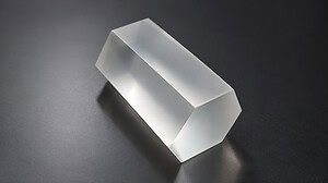
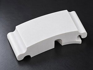
Consider a brittle component where edge breakout and a repeating surface pattern matter more than nominal feed speed. A useful comparison is to cut representative samples with equivalent fixture support and acceptance criteria, then record the motion mode, wire, total cycle, kerf, straightness, edge condition and surface marks. The preferred method is the one that repeatedly produces accepted parts, not the one with the highest unloaded wire speed.
When the requirement changes to several parallel slices, machine capacity and load distribution may outweigh the directional-motion preference. This is why single-wire and multi-wire systems should be compared as complete processes rather than by one feature.
Wire Speed, Tension, Feed and Reversal
Direction is only one parameter. Wire speed changes abrasive engagement and debris transport; tension stabilizes the path; feed determines cutting load; cooling or extraction manages particles. In a reciprocating system, acceleration and reversal settings add another variable. Change one factor at a time and record the result. See the supporting wire speed, tension and feed rate guide for the basic parameter relationship.
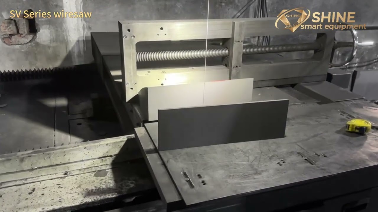
Wire Cutting Application Video
The retained video shows a wire cutting application. Use it to observe the machine and wire path, not as a universal parameter recommendation. The workpiece material, dimensions, fixture, wire and quality target must be compared with the intended project.

Selection Checklist
- Identify the material, dimensions, cut depth and number of simultaneous cuts.
- Define measurable acceptance limits for kerf, straightness, chipping and surface condition.
- Confirm whether the process needs a closed-loop wire, finite reciprocating wire or multi-wire layout.
- Compare fixture access, debris removal and the effect of reversal on the actual workpiece.
- Measure total cycle, wire consumption and accepted yield instead of relying on a motion label.
For a broader comparison of available machine configurations, review the diamond wire saw product category. Final selection should be confirmed from the actual workpiece and required result.
よくある質問
Is unidirectional cutting always more accurate?
No. It removes the programmed reversal event, but accuracy still depends on machine alignment, wire condition, tension, feed, fixture and material behavior.
Is bidirectional cutting always faster?
No. Productivity must include acceleration, reversal, cutting load, setup, wire use and accepted yield. Compare the complete cycle on the intended machine.
Can one machine switch between both directions?
That depends on the machine’s drive, wire path and control design. Confirm the supported motion modes with the specific model rather than assuming every system can switch.
Which motion is suitable for multi-wire cutting?
Multi-wire machines can use different motion architectures. Pitch, total cutting load, workpiece support and control strategy are more useful selection factors than direction alone.
Conclusion: Choose by the Complete Cutting Process
Unidirectional and bidirectional cutting describe different wire motions, but neither label guarantees a better result. Select the process by machine architecture, workpiece, number of cuts, fixture, wire, debris control and measurable acceptance criteria. A representative sample cut remains the most reliable way to compare quality, cycle time and wire use.