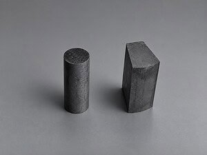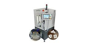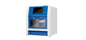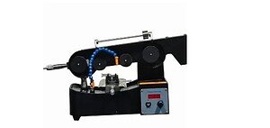
Если вы режете ИИГ или ГГГ гранат для фаpадеевских вращателей, вам нужна алмазная проволочная пила — в частности, с системой контроля натяжения проволоки с обратной связью и прецизионным приспособлением для ориентации. Стандартные пилы для резки дают слишком большую потерю материала (керф) и слишком сильное повреждение подповерхностного слоя для граната оптического качества. На этой странице рассказывается, какие машины подходят, как их настроить для ИИГ и ГГГ, а также какие параметры установить с первого реза.
Для получения справочной информации о резке граната в приложениях фаpадеевских вращателей см. наш резка граната для фаpадеевских вращателей обзор.
Что такое станок для резки гранатовых кристаллов?
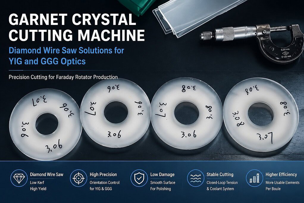
Станок для резки гранатовых кристаллов — это алмазная проволочная пила, настроенная для резки булей ИИГ (иттрий-железный гранат) или ГГГ (гадолиний-галлиевый гранат) на заготовки или стержни оптического качества. Ключевое отличие от универсальной проволочной пилы заключается в конфигурации станка: диаметр проволоки, соответствующий размеру буля (0,35–0,65 мм), низкая скорость подачи, контроль натяжения с обратной связью и система крепления, которая сохраняет кристаллографическую ориентацию на протяжении всего реза.
Эти станки выполняют одну основную функцию: разделение материала буля на элементы, которые идут непосредственно на полировку, с достаточным качеством поверхности и точностью ориентации, чтобы этап полировки мог достичь конечных оптических спецификаций без доработки.
Какой станок для резки гранатовых кристаллов следует использовать?
Ответ зависит от вашего материала и размера буля:
| Приложение | Рекомендуемый станок | Почему |
|---|---|---|
| ИИГ стержни для фаpадеевских вращателей (буль Ø 20–50 мм) | SG20 | Компактный путь проволоки, регулируемое натяжение, совместимое приспособление для ориентации |
| Пластины подложки ГГГ (шар Ø 50–100 мм) | SG40 | Большая вместимость шара, многоточечная опция резки для более высокой производительности |
| Смешанное производство YIG + GGG | SG40 со сменными приспособлениями | Одна платформа, два набора приспособлений — аппаратная замена не требуется |
Как SG20, так и SG40 используют одну и ту же технологию алмазной проволочной петли, одну и ту же систему натяжения с обратной связью и совместимы с охлаждающей жидкостью на водной основе для резки оптических кристаллов. Разница заключается в диаметре шара и конфигурации производительности.
Если вы в настоящее время используете пилу с внутренним диаметром (ID) для резки граната и сталкиваетесь с высоким уровнем брака или смещением ориентации, переход на SG20 является наиболее прямым решением — см. раздел сравнения ниже.
Алмазная проволочная пила против пилы с внутренним диаметром: какая лучше режет гранат?
Большинство операций, которые переходят с пилы с внутренним диаметром на алмазную проволочную пилу для граната, делают это из-за двух проблем: потери на пропил и уровня брака. Вот как две технологии сравниваются по важным показателям:
| Параметр | Алмазная проволочная пила | Пила с внутренним диаметром |
|---|---|---|
| Ширина пропила | 0,35-0,65 мм | 0,8–1,5 мм |
| Subsurface damage | Ниже — только абразивное удаление | Выше — изгиб лезвия добавляет ударную нагрузку |
| Смещение ориентации во время резки | Нет — проволока не имеет боковой жесткости для отклонения | Возможно — изгиб лезвия может сместить угол резки |
| Доступ охлаждающей жидкости | Непрерывно по всей длине проволоки | Ограничено зоной входа лезвия |
| Уровень брака на ИИГ | Низкий при правильных параметрах | Выше — резонанс и изгиб лезвия вызывают трещины на кромке |
| Элементы, полученные из 50-миллиметрового буля | +1 к +2 по сравнению с пилой ID | Исходный уровень |
Преимущество по ширине реза прямое: на 50-миллиметровом буле ИИГ, разрезанном на элементы толщиной 5 мм, уменьшение ширины реза с 1,2 мм (пила ID) до 0,50 мм (алмазная проволока) позволяет получить один-два дополнительных элемента из буля. При стоимости материала ИИГ такое восстановление быстро накапливается в ходе производственного цикла.
Преимущество по повреждению подповерхностного слоя влияет на выход полировки. Лезвия пилы ID изгибаются под нагрузкой, что вызывает ударную нагрузку на поверхности реза в дополнение к истиранию. Это ударное повреждение проникает глубже в кристалл, чем простое истирание — это означает больше времени на шлифовку перед полировкой и более высокий риск появления остаточного рассеяния при окончательном оптическом контроле.
Для получения более подробной информации о том, как конфигурация петли проволоки влияет на качество реза, см. наш петли из алмазной проволоки руководство.
Как настроить станок для резки гранатовых кристаллов
Как только у вас есть подходящая машина, четыре параметра определяют, соответствуют ли ваши первые разрезы спецификациям или отправятся на доработку.
1. Диаметр проволоки
| Тип буля | Рекомендуемый диаметр проволоки | Ширина пропила |
|---|---|---|
| ИИГ (Ø 20–40 мм, короткие стержни) | 0,35–0,50 мм | ~0.40–0.55 мм |
| YIG/GGG (Ø 40–75 мм) | 0.50–0.65 мм | ~0.55–0.70 мм |
| GGG (Ø 75–100 мм, подложки) | 0.55–0.65 мм | ~0.60–0.70 мм |
Начните с 0.50 мм для YIG, если вы впервые устанавливаете параметры — это обеспечивает баланс между потерями на резе и стабильностью проволоки. Более тонкая проволока (0.35 мм) уменьшает рез, но более чувствительна к изменению натяжения; переходите к ней только после подтверждения базовых параметров.
2. Натяжение проволоки
Поддерживайте натяжение в диапазоне от низкого до среднего для граната. Точное значение зависит от машины и диаметра проволоки, но правило таково: натяжение достаточное для поддержания прямолинейности пути проволоки, не более. Избыточное натяжение создает напряжение в кристалле в точке резки и инициирует растрескивание по плоскостям спайности {110} — наиболее частая причина потери элемента в середине резки на YIG.
Замкнутая система контроля натяжения не является опцией для граната. Ручные или разомкнутые системы натяжения допускают кратковременные скачки — от ускорения проволоки, перехода катушки или зацепления проволоки — достаточные для растрескивания элемента YIG, который в противном случае резался бы чисто.
Для справки по процедурам калибровки натяжения см. наш скорость проволоки, натяжение и скорость подачи страница.
3. Скорость подачи
Установите скорость подачи ниже, чем для кремния того же диаметра. YIG и GGG тверже, чем стекло из оксида кремния, но более склонны к растрескиванию. Практический метод: начните медленно, увеличивайте на 10% шага за проход, пока не увидите первый скол края при выходе кристалла, затем уменьшите на 25% и зафиксируйте эту скорость.
Сколы на торце кристалла — где проволока прорывается через последнюю долю материала — являются наиболее распространенным режимом отказа при подаче на гранате. Уменьшение скорости подачи для последних 0.5–1.0 мм резки устраняет большинство сколов на выходе, не замедляя значительно общий цикл.
4. Охлаждающая жидкость
Используйте водорастворимый охлаждающий раствор при непрерывном потоке — без перерывов. Гранат чувствителен к термическим градиентам: прерывистое охлаждение вызывает локальный нагрев на поверхности реза, что приводит к образованию трещин от термического напряжения, особенно в более длинных элементах. Формула с нейтральным pH предотвращает повреждение поверхности кристалла из-за кислой или щелочной химии охлаждающего раствора.
Для настройки системы охлаждения и рекомендаций по скорости потока см. наш Охлаждение и смазка при распиловке проволоки справочник.
ИИГ против ГГГ: Что меняется в настройках?
Одна и та же машина, разные приоритеты. Вот что вам действительно нужно настроить между прогонами ИИГ и ГГГ:
| Элемент настройки | ИИГ (Фарадеевский ротатор) | ГГГ (Подложка) |
|---|---|---|
| Тип крепления | Крепление для ориентационного эталона — обеспечивает выравнивание кристаллографической оси | Стандартное крепление для подложки — удерживает слиток перпендикулярно проволоке |
| Основной показатель качества | Отклонение оптической оси (≤ ±0,5° типично) | TTV (общий перепад толщины), от подложки к подложке |
| Приоритет скорости подачи | Качество прежде всего — медленно, стабильно | Пропускная способность — может работать быстрее, чем YIG |
| Осмотр после резки | Проверка ориентации перед полировкой | Измерение TTV |
| Частота смены проволоки | Чаще — требования к поверхности YIG более строгие | Стандартный интервал |
Вам не нужны отдельные машины для YIG и GGG. Вам нужны отдельные приспособления и отдельные наборы параметров, сохраненные в контроллере машины. При переключении между материалами смените приспособление, загрузите набор параметров, выполните одну квалификационную резку, осмотрите, затем продолжайте.
Машина для резки гранатовых кристаллов: выбор правильной конфигурации
Если ваша основная проблема — высокий процент брака при существующем производстве YIG:
Проблема почти всегда заключается в одной из трех вещей: скачки натяжения, вызывающие растрескивание элементов, слишком высокая скорость подачи, вызывающая сколы на выходе, или прерывание подачи охлаждающей жидкости, вызывающее термические трещины. SG20 с системой контроля натяжения с обратной связью решает все три проблемы при правильной настройке параметров.
Если ваша основная проблема — низкий выход с буля (слишком много резок уходит в пропил):
Переключитесь с пилы с внутренним диаметром на проволочную пилу. SG20 с диаметром проволоки 0,35–0,50 мм режет пропил шириной 0,40–0,55 мм по сравнению с 0,8–1,5 мм на типичной пиле с внутренним диаметром. На материале YIG такое уменьшение пропила напрямую увеличивает количество пригодных элементов с буля.
Если вам нужно резать как стержни YIG, так и пластины GGG при производственном объеме:
SG40 с двумя комплектами оснастки справляется с обоими. Большая вместимость булей машины охватывает диаметры подложек GGG, которые SG20 не может вместить, в то время как сменная система оснастки позволяет выполнять критические по ориентации разрезы YIG на той же платформе без смены оборудования.
Свяжитесь с нами по адресу levy@endlesswiresaw.com чтобы обсудить вашу установку для резки граната, или посмотрите нашу станки для огранки драгоценных камней страницу с информацией о связанных применениях оптических кристаллов.
ЧАСТО ЗАДАВАЕМЫЕ ВОПРОСЫ
Какова наиболее частая причина растрескивания граната YIG при резке?
Скачки натяжения проволоки. Когда натяжение превышает порог напряжения на плоскостях спайности граната {110} — вызванные зацеплением проволоки, переходом катушки или резким изменением скорости подачи — элементы ломаются в середине резки. Замкнутый контур управления натяжением устраняет это, поддерживая натяжение в узком диапазоне независимо от изменения скорости проволоки.
Могу ли я использовать ту же машину, что и для кремния, для резки граната YIG?
Да, если она имеет замкнутый контур управления натяжением и принимает проволоку в диапазоне 0,35–0,65 мм для работы с оптическими кристаллами. Оборудование то же; меняется набор параметров. YIG работает при более низком натяжении и более медленной скорости подачи, чем кремний, и требует оснастки для кристаллографической ориентации, которая не нужна при резке кремния.
Как узнать, достаточно ли хорошее качество моей поверхности после резки для полировки?
Проверьте глубину подповерхностного повреждения относительно вашего бюджета на полировку. Если вы можете отполировать 100–150 мкм с каждой поверхности, и остаточное рассеяние не появляется, качество режущей поверхности адекватно. Если рассеяние появляется в пределах бюджета на полировку, уменьшите скорость подачи и проверьте прерывания подачи охлаждающей жидкости — оба являются распространенными источниками более глубокого, чем ожидалось, подповерхностного повреждения.