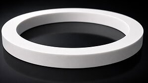
Кольцо из керамики на основе оксида алюминия толщиной 10 мм. Один разрез. Две пригодные для использования детали.
Это не стандартная задача по резке. Геометрия здесь представляет собой проблему — и это полезный пример для понимания того, что на самом деле означает точность при резке современных керамических материалов.
Применение: Одна заготовка, два готовых кольца
Цель заказчика заключалась не в том, чтобы разрезать кольцо пополам вдоль оси. Им нужно было разделить одно керамика кольцо радиально — одним разрезом через стенку кольца — чтобы одновременно получить два концентрических кольца разного диаметра. Внутреннее кольцо и внешнее кольцо должны были стать готовыми деталями.
Такой подход имеет смысл с точки зрения использования материала. Вместо того чтобы изготавливать два отдельных кольца из двух отдельных заготовок, вы производите оба из одной заготовки. Меньше потребляется сырья, меньше настроек оснастки, меньше этапов процесса. Теоретически, это эффективный подход.
На практике геометрия практически не оставляет места для ошибок.

Что на самом деле требуется по чертежу
Критические размеры следующие:
- Внутренний диаметр внешнего кольца: 265,5 мм
- Внешний диаметр внутреннего кольца: 264,7 мм
- Разница между этими двумя поверхностями: 0,8 мм
Этот зазор в 0,8 мм — это все пространство, доступное для прохождения режущей проволоки, включая сам пропил.
При использовании 0,25 мм петля из алмазной проволоки, ширина пропила составляет примерно 0,30–0,35 мм (диаметр проволоки плюс выступ зерна с обеих сторон). Это оставляет общее окно допуска по положению примерно 0,4 мм, разделенное поровну между двумя сопрягаемыми поверхностями.
В абсолютных величинах: каждая обработанная поверхность имеет примерно 0,15–0,20 мм допустимого отклонения от номинала, прежде чем деталь выйдет из допуска.
Почему это окно допуска действительно сложное
0,15 мм не звучит катастрофично, пока вы не начнете перечислять вещи, которые могут его поглотить:
Отклонение проволоки под нагрузкой. Когда проволока входит в материал, боковые режущие силы отклоняют проволоку в сторону. В жесткой, правильно натянутой системе это отклонение минимально. В плохо настроенной системе изгиб проволоки сам по себе может превышать 0,1 мм. Правильная калибровка натяжения проволоки необходима для удержания отклонения в пределах бюджета.
Тепловое расширение. Машина, работающая в течение нескольких часов, испытывает тепловое расширение рамы, шпинделя и направляющих. На чугунной рама машины это может составлять 20–50 мкм в зависимости от условий окружающей среды.
Колебания натяжения проволоки. Если система натяжения допускает даже кратковременные падения натяжения во время резки — из-за колебаний сервопривода, подшипника шкива с повышенным трением или слишком медленного контура обратной связи по натяжению — проволока будет кратковременно отклоняться дальше номинального положения. Вы не увидите, как это происходит; вы увидите это на детали.
Вибрация. Любой резонанс, вызванный проволокой при скорости 30–60 м/с, который передается на ось подачи проявится как периодическая погрешность поверхности. На таком тонком кольце (10 мм) даже вибрация с малой амплитудой может вызвать локальное превышение реза вблизи точек входа и выхода.
Совокупный эффект этих факторов — это то, что инженеры-технологи называют “бюджетом погрешностей”. При допуске в 0,15 мм почти нет запаса для компенсации даже одного из них — не говоря уже о совокупном вкладе всех четырех.

Как должна быть настроена технологическая операция
Для такого рода применения правильная геометрия означает контроль процесса до начала резки, а не его корректировку после.
Выбор проволоки имеет немедленное значение. Проволока диаметром 0,25 мм дает лишь достаточно места для резки. Переход на проволоку диаметром 0,30 мм сократит допустимый допуск до такой степени, что он станет ненадежным для производства. Диаметр проволоки должен выбираться относительно допуска на чертеже, а не наоборот.
Скорость подачи должна быть консервативной. Оксид алюминия (Al₂O₃) твердый и хрупкий — твердость по Виккерсу обычно в диапазоне 1500–1800 HV в зависимости от чистоты и плотности спекания. Скорости подачи для спеченного оксида алюминия с проволокой диаметром 0,25–0,55 мм обычно составляют от 2 до 8 мм/мин. Увеличение скорости подачи для увеличения производительности в таком приложении с жесткими допусками — это способ получения брака. Понимание взаимосвязи между скорость проволоки, натяжение и скорость подачи имеет решающее значение.
Крепление детали должно быть жестким. Кольцо должно быть закреплено так, чтобы оно не могло смещаться радиально во время резки. Любое смещение детали относительно траектории проволоки напрямую увеличивает погрешность размеров. На цилиндрической заготовке без плоской опорной поверхности это обычно означает изготовление специального приспособления или использование мягких кулачков, которые захватывают наружный диаметр без искажений.
Зоны входа и выхода реза являются точками риска. Когда проволока входит в стенку кольца, длина контакта мала, а боковая сила асимметрична. То же самое при выходе. Эти две точки являются наиболее вероятными местами отклонения от намеченной траектории реза. Снижение скорости подачи на входе и выходе — даже на 30–40% — может значительно снизить этот риск.
Подача охлаждающей жидкости должна достигать всей зоны реза. В случае кольцевой геометрии дуга резания длинная по сравнению с резанием плоской плиты. Охлаждающая жидкость должна направляться так, чтобы следовать за проволокой в стенку кольца на протяжении всего реза — а не только в точке входа. Недостаточное охлаждение на средней глубине реза создает тепловые градиенты, которые могут вызвать микротрещины в оксиде алюминия.
Что этот случай демонстрирует о требованиях к станку
Много маркетинга алмазно-проволочных станков сосредоточено на максимальной скорости резания или максимальном размере заготовки. Для этого применения ни одна из этих характеристик не имеет значения.
Важно:
Жесткость рамы — предотвратить прогиб конструкции станка под нагрузкой натяжения проволоки. Жесткая конструкция и каркас машины гарантирует, что траектория проволоки остается там, где вы ее установили, а не там, куда ее уводит прогиб рамы. При диаметре реза 265 мм с допуском 0,15 мм даже 30 мкм прогиба рамы составляют 20% вашего бюджета погрешности, израсходованного до того, как проволока коснется заготовки.
Полоса пропускания регулирования натяжения — скорость, с которой система натяжения корректирует отклонения. Медленно реагирующая система позволяет проволоке кратковременно изгибаться во время переходных процессов силы резания (например, при пересечении внутренней поры или неоднородности плотности в керамике). Чем быстрее коррекция, тем точнее контроль размеров.
Термическая стабильность — насколько изменяются размеры станка в течение времени резания. Кольцо такого размера требует времени для резания. Если станок увеличивается на 40 мкм в процессе, ваша позиция реза смещается на 40 мкм вместе с ним. Хорошая термическая конструкция (симметричная рама, охлаждающая жидкость с контролем температуры, протокол прогрева) делает это смещение предсказуемым и управляемым.
Мониторинг процесса — обратная связь в реальном времени по натяжению проволоки, силе подачи и положению проволоки. При резании с жесткими допусками вам нужно знать во время резания, находитесь ли вы на правильном пути — а не обнаружить постфактум, что деталь является браком. Системы мониторинга, которые регистрируют данные о натяжении и силе, также помогают вам диагностировать первопричину, когда что-то идет не так.
Бюджет погрешности в цифрах
Вот как общий бюджет в 0,4 мм распределяется в хорошо контролируемом процессе:
| Источник погрешности | Типичный вклад | Контролируемый вклад |
|---|---|---|
| Ширина реза (проволока 0,25 мм) | 0,30–0,35 мм | 0,30–0,35 мм (фиксировано) |
| Отклонение проволоки под нагрузкой | 0,05–0,15 мм | 0,02–0,04 мм |
| Тепловое расширение (станка) | 0,02–0,05 мм | 0,01–0,02 мм |
| Колебание натяжения | 0,02–0,08 мм | 0,01–0,02 мм |
| Вибрационно-индуцированное перекрытие | 0,01–0,05 мм | < 0,01 мм |
| Всего потреблено | 0,40–0,68 мм | 0,35–0,44 мм |
| Доступный бюджет | 0,80 мм | 0,80 мм |
Левая колонка показывает, что происходит на стандартной машине с базовым контролем натяжения. Цифры не сходятся — общая погрешность превышает бюджет, что означает невозможность стабильного производства; вы полагаетесь на удачу.
Правая колонка показывает, чего можно достичь с жесткой рамой, быстрым контролем натяжения, терморегулированием и правильной настройкой процесса. Цифры близки, но выполнимы. В этом разница между машиной, которая может выполнить эту работу, и той, которая не может.

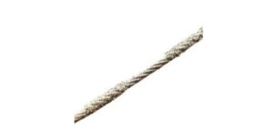
Почему бесконечная алмазная проволока — правильный инструмент для этой резки
Это применение требует бесконечная петля из алмазной проволоки вместо подхода с открытой проволокой или лезвием по нескольким причинам:
Стабильное состояние проволоки. Бесконечная петля представляет одну и ту же алмазную абразивную поверхность заготовке на протяжении всей резки. Нет градиента износа от начала до конца катушки — ширина реза остается постоянной, что является обязательным условием, когда общий бюджет допуска составляет 0,4 мм.
Непрерывный путь резки. Петля движется в одном направлении без реверса. Отсутствие возвратно-поступательного движения означает отсутствие артефактов ускорения при смене направления, что устраняет источник периодической ошибки поверхности на режущей грани.
Возможность тонкого пропила. Бесконечные алмазные проволочные петли доступны в диаметрах от 0,25 мм, обеспечивая ширину пропила 0,30–0,35 мм. Это минимальный практический пропил для производства резка керамики с использованием алмазной проволоки — и именно это требуется для данного применения.
Предсказуемый срок службы проволоки. Поскольку петля представляет собой замкнутую систему известной длины, алмазная загрузка и скорость износа могут быть точно охарактеризованы. Это означает, что вы можете предсказать, когда следует заменить проволоку, прежде чем она начнет работать хуже — вместо того, чтобы обнаружить в середине резки, что проволока потеряла абразивность и теперь отклоняется больше, чем ожидалось.
Практический вывод
Данное применение для резки керамического кольца является полезным эталонным случаем. Не потому, что каждому клиенту нужно разрезать керамическое кольцо диаметром 265 мм — а потому, что выявленные инженерные принципы применимы к любой задаче точной резки:
- Начинайте с допуска на чертеже, а не со спецификации станка. Бюджет допуска определяет, какой диаметр проволоки, какой класс станка и какие параметры процесса являются жизнеспособными.
- Перечислите все источники ошибок и назначьте им бюджет. Если сумма превышает допуск, вам нужен лучший станок или другой процесс — никакой навык оператора не компенсирует физику.
- Возможности станка, которые важны для точности, — это не те, которые указаны в брошюре. Жесткость рамы, полоса пропускания регулирования натяжения и термическая стабильность определяют, сможете ли вы выдержать допуск. Максимальные обороты и максимальный размер заготовки — нет.
- Протестируйте перед тем, как приступить к производству. Отправьте нам вашу керамическую заготовку и чертеж. Мы проведем тестовую резку на нашем оборудовании и вернем детали с данными размерной инспекции. Это более надежный способ оценки возможностей, чем сравнение спецификаций.
Для резки керамических колец и других передовых керамических применений изучите наши керамические режущие решения или свяжитесь с нашей инженерной командой, предоставив геометрию вашей заготовки и требования к допускам.