Proper machine alignment serves as the absolute physical foundation for precision cutting in brittle materials. In the manufacturing of advanced ceramics, silicon carbide, and sapphire, the accuracy of diamond wire saw machinesdetermined long before the spindle is powered on. Even the most advanced PLC programming servo tracking algorithms cannot compensate for a twisted machine frame or angularly misaligned pulleys. This guide covers the complete installation and alignment protocol, detailing the strict engineering procedures required from foundation preparation to the final no-load diagnostic run.
Site Preparation and Foundation Requirements
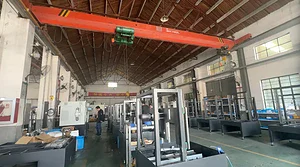
The operational environment dictates the baseline stability of the equipment. Industrial wire saws operate with microscopic tolerances, requiring isolation from external factory variables before any mechanical assembly begins.
Concrete Foundation and Vibration Isolation
High-precision cutting generates internal dynamic loads, and the machine must be insulated from external low-frequency vibrations transmitted through the factory floor.
Concrete Thickness: The designated concrete foundation must range from 300 mm to 500 mm in thickness, engineered specifically to handle the total static mass and dynamic operational loads of the specific machine model. Steel rebar reinforcement should be utilized to prevent structural cracking.
Vibration Isolation: In facilities operating heavy stamping presses, forging equipment, or aggressive CNC milling centers, a dedicated vibration isolation trench is mandatory. This trench isolates the wire saw’s foundation slab from the surrounding floor and is typically filled with specialized dampening materials, such as specific grades of vibration-absorbing sand or industrial rubber padding.
Curing Time: Fresh concrete must undergo a complete 28-day curing cycle. Anchoring heavy equipment to green concrete guarantees microscopic shifting and foundation shrinkage, which will permanently destroy the machine’s leveling accuracy over the first few months of operation.
Unpacking and Initial Positioning
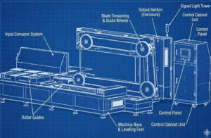
Lifting and positioning require strict adherence to the manufacturer’s rigging diagrams. Rigging teams must exclusively use the designated lifting points cast into the primary base.
Forklifts or overhead cranes must never apply lateral or vertical pressure to the electrical cabinets, guide wheel shafts, or the tension dancer arm assemblies. Applying load to a guide wheel shaft can induce a permanent bending deformation of 0.05 mm or more, instantly rendering the shaft useless for precision operation.
Once the machine is lowered onto the preset foundation anchor points, the initial rough positioning is complete, and the geometric calibration phase begins.
The Precision Leveling Process
The leveling process eliminates structural stress from the machine base. Bolting down an unlevel chassis forces the cast iron or welded steel machine framet wist. This torsion transfers directly into the linear guide rails and bearing housings, causing the wire path to deviate and the cutting wire to jump at high speeds.
Tools Required for Machine Leveling
Standard construction bubble levels are inadequate for industrial equipment installation. Execution requires specialized metrology instruments:
Master Precision Machinist Levels: These instruments must possess a certified measurement resolution of ≤ 0.02 mm/m (20 microns of deviation per linear meter).
Laser Trackers or Optical Levels: For multi-wire saws or extended-length machines where the bed exceeds standard straightedge spans, optical systems verify that the entire linear bed remains perfectly flat without microscopic bowing.
Step-by-Step Leveling Procedure
Leveling a rigid body on multiple points is an iterative engineering process.
1. Placement of Mounts: Install the heavy-duty leveling wedges or anti-vibration machine feet under all designated load-bearing nodes of the chassis.
2. Rough Leveling: Utilize a standard spirit level to bring the entire machine within a preliminary 1 mm/m tolerance. This establishes a baseline for precision adjustments.
3. Cross-Hatch Measurement: Place the master precision machinist level directly onto the machined reference surfaces of the primary base (typically the mounting flats for the linear guide rails). Measure the deviation along the X-axis (parallel to the wire travel direction) and the Y-axis (perpendicular to the wire path).
4. Iterative Adjustment: Adjust the leveling wedge bolts in small increments. Because the rigid machine frame distributes weight statically, raising one corner alters the load and levelness of the other three. This sequence must be repeated iteratively until the deviation across all reference planes is strictly ≤ 0.02 mm/m.
5. Locking and Stress Release: Once the target tolerance is achieved, lock the leveling nuts. The machine must then sit undisturbed for 24 hours. This dwell time allows the residual mechanical stresses within the casting and frame to settle. After 24 hours, engineers must verify the levelness again before executing the final foundation grouting or anchor bolt torquing.
A proper precision setup at this stage prevents downstream calibration failures that no software adjustment can resolve.

Guide Wheel Alignment and Coplanarity
With base-level machine alignment confirmed, the focus shifts to the dynamic components. The main drive wheel, all guide wheels, and tension pulleys must operate in flawless geometric harmony.
Why Coplanarity Matters
In a closed-loop system, the cutting wire travels at velocities reaching 60 m/s. For stable operation, the V-grooves or U-grooves of every wheel in the wire path must be strictly coplanar—existing within the exact same mathematical two-dimensional plane.
Failing to achieve strict guide wheel alignment produces immediate negative consequences:
Surface Waviness: A misaligned wheel forces the wire to climb the sidewall of the groove before snapping back to the center. This micro-jumping translates directly into the cut, leaving severe wave patterns and lines on the material surface.
Component Degradation: The lateral scraping action rapidly shreds the polyurethane (PU) or rubber groove linings, requiring premature replacement and causing unwanted machine downtime.
Wire Failure: Angular friction introduces severe torsional stress to the diamond wire loop leading to premature fatigue, joint failure, and sudden wire breakage during operation.
Alignment Measurement Methods
Validating a precision setup requires exact measurement techniques rather than visual estimation.
Dial Indicators (Dial Gauges): Mounted via a rigid magnetic base to the machine bed, the indicator probe rests against the machined side face of the guide wheel. By manually rotating the wheel, engineers measure the axial runout (wobble). Total indicated runout must remain < 0.01 mm.
Precision Straightedge and Feeler Gauges: A certified straightedge bridges the end faces of multiple pulleys. Feeler gauges probe for any microscopic gaps, verifying parallel alignment across the entire wheel array.
Laser Alignment Tools: An emitter mounts to the primary drive wheel groove, projecting a continuous laser beam to target sensors mounted on the subsequent guide wheels. This system provides real-time, quantifiable data on both angular and parallel offset deviations in the wire path.
Thermal Expansion Considerations
Spindles operating at 4000 RPM generate internal friction and heat, which transfers to the shaft and bearing housings. The differing thermal expansion coefficients of steel and cast iron mean the machine dimensions change slightly at operating temperature. Alignment must be measured in a cold state, and then re-verified after the machine completes a thermal warm-up cycle to guarantee dynamic stability under load.
Integration with the Control System
Mechanical calibration and electronic control response are inseparable. Software algorithms cannot repair mechanical defects; mechanical perfection must precede electronic integration.
If the machine alignment is compromised, the resulting friction within the pulley bearings and the lateral scraping of the wire inside the grooves generate erratic, unpredictable force loads. The system registers this mechanical noise as tension fluctuations. Consequently, the tension control system distorted feedback and initiates continuous, aggressive overcorrections, destabilizing the pneumatic cylinders or servo motors.
Attempting to execute a standard wire tension calibration a misaligned machine is a flawed process. The excessive parasitic friction in the misaligned wire path distorts the static calibration weight readings, rendering the load cell data inaccurate before the machine ever attempts a cut.
Final Verification — Dry Run and Vibration Analysis
The final phase of installation transitions from static measurement to dynamic testing, ensuring the assembled components perform under operational speeds without destructive harmonic resonance.
Dry Run Procedure
The dry run initiates the system without cutting material engaged.
Engineers power the drive system and gradually ramp the wire speed from a baseline of 10 m/s up to the maximum operational velocity (e.g., 60 m/s).
During the acceleration curve, operators visually and instrumentally monitor the wire path. The wire must track perfectly center-groove without excessive bowing, lateral vibration, or flutter.
FFT Vibration Diagnostics
High-end industrial installations utilize vibration transducers temporarily mounted to the main spindle housing and critical guide wheel bearing blocks.
Using Fast Fourier Transform (FFT) analysis, engineers isolate and identify specific vibration frequencies in the time-waveform data.
A high vibration amplitude matching the 1X rotational frequency (1X RPM) indicates a statically or dynamically unbalanced wheel or pulley.
High-frequency, non-synchronous noise spikes identify defective rolling elements within a bearing or subtle, residual misalignment forcing the shaft into a bind.
The machine is only certified and handed over for the active diamond wire saw cutting process the FFT vibration signature falls completely within the manufacturer’s acceptable baseline parameters.

Conclusion
Cutting corners during the leveling process or rushing through guide wheel coplanarity checks guarantees poor material yield and excessive consumable costs. Precision cannot be forced via software adjustments during the cut; it must be physically built into the machine framework before the diamond wire ever touches the ingot. Committing to a rigorous, data-driven precision setup directly ensures maximum wire lifespan, superior TTV metrics, and the long-term operational reliability required by modern diamond wire saw cutting technology
FAQ
Q1: How often should machine alignment be checked?
Standard industrial protocols dictate that machine alignment should be verified every 6 months or during major preventive maintenance cycles. Immediate recalibration is mandatory following a severe machine crash, wire break at high load, or the replacement of heavy structural components like the spindle or main drive wheel.
Q2: Can I use a standard construction level for the leveling process?
No. Standard construction bubble levels completely lack the resolution required for precision equipment. You must use a master precision machinist level with a certified accuracy of ≤ 0.02 mm/m to prevent imperceptible micro-torsion in the machine bed.
Q3: What is the first sign of poor guide wheel alignment?
The most immediate physical indicator is uneven, asymmetrical wear on the polyurethane or rubber guide wheel grooves. On the product side, the sudden appearance of cutting marks or visible lines (surface waviness) on the cut wafers strongly suggests the wire is micro-jumping due to pulley misalignment.