Technical Article
1. Joint Design: The Underrated Variable in Precision Machining
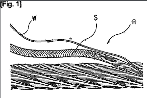
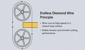
In the technical hierarchy of endless wire saw systems, the loop joint design is a critical factor that determines more than just whether the wire will break; it directly dictates the TTV (Total Thickness Variation) and surface roughness of the sliced wafer. When a loop rotates at a linear velocity of 80 m/s, the joint enters the cutting zone approximately 30 to 40 times per second. If the joint possesses even a micron-level geometric protrusion, this high-frequency impact will trigger micro-crack propagation in brittle materials like SiC. Therefore, when evaluating diamond wire loops, engineers must treat the joint as a precision dynamic component rather than a mere connection point.

2. Why Semiconductor-Grade Slicing Must Abandon Welding
While laser welding is common in general industrial applications, it presents three insurmountable physical flaws in high-precision loop joint design:
- Microstructural Embrittlement: The rapid heating and cooling cycles of welding cause a martensitic transformation in the high-carbon steel core. While the Tensile strength (Wikipedia link) might meet static standards, the toughness is severely compromised, leading to premature fatigue failure under continuous bending.
- Modulus Mismatch: A weld bead acts as a rigid sphere, whereas the original wire possesses elastic flexibility. This sudden change in modulus causes the wire to “jump” or vibrate when passing over small-diameter pulleys, a phenomenon documented in our loop structure design research.
- Abrasive Loss: The extreme heat of welding burns off the surrounding diamond coating, creating a “cutting dead zone” that disrupts the continuity of material removal rates.
3. Manual Interweaving & Composite Plating: The Only Seamless Logic
To achieve truly “silent” operation at high speeds, the industry’s most advanced process utilizes a combination of Manual Interweaving and Composite Electroplating.
3.1 Mechanical Distribution of Fiber-Level Splicing
Technicians use microscopic guidance to unravel the individual filaments at the wire ends and interweave them according to a specific spatial topology.
- Stress Dispersion: The interweaving zone typically spans 80mm to 120mm. This allows tension to be transmitted via a gradient of frictional forces between the filaments, eliminating the stress concentration found in single-point connections and significantly enhancing tension stability.
- Geometric Pre-control: This artisan process ensures that the diameter increase at the joint is virtually negligible before it even enters the electroplating stage.
3.2 Chemical Anchoring of the Nickel Matrix and Isotropic Diameter Control
Following the interweaving, the joint enters a specialized electroplating bath for controlled deposition.
- Penetration and Anchoring: Nickel ions, driven by an electric field, penetrate deep into the gaps of the interwoven strands, forming a molecular-level mechanical anchor. This not only reinforces the joint but provides an ideal substrate for diamond particles.
- Uniform Growth Technology: By monitoring current density in real-time, we maintain the final diameter deviation at the joint within ±2μm. This extreme precision is key to preventing mechanical resonance during high-speed rotation.
- Grit Co-deposition: High-strength synthetic diamond particles are co-deposited during the nickel plating, ensuring the joint is as abrasive and durable as the main body of the wire.
4. Dynamic Verification: Zero-Impact Performance at 80 m/s
When the loop joint design achieves physical continuity, its performance in high-speed scenarios is transformative:
- Vibration Suppression: The mass-per-unit-length at the joint remains consistent with the rest of the wire, eliminating centrifugal vibrations induced by eccentric forces.
- Lifespan Extension: Due to the absence of thermal damage, the fatigue life at the joint is increased by more than 2x. Verification of these metrics can be found in our loop lifespan and testing protocols.
- Surface Quality: This seamless transition effectively eliminates “wire marks” on 6-inch SiC wafers, subsequently reducing the required downstream polishing time by 20%.

5. FAQ: Engineering Inquiries on Loop Joint Technology
Q1: Can the tensile strength at the joint reach 100% of the original wire?
A1: A loop joint design utilizing manual interweaving and composite plating typically achieves 90%-95% of the original wire’s static breaking load. However, because the interwoven structure offers superior dynamic toughness, its performance in loop vibration control often exceeds that of welded joints.
Q2: Why do some joints generate excessive heat during the cutting process?
A2: If a joint diameter exceeds tolerances (a bulge), friction with the workpiece increases exponentially, generating localized heat. Our uniform diameter technology (±2μm) ensures the joint passes smoothly through the kerf, effectively controlling thermal accumulation.
Q3: How can one visually distinguish a high-quality joint?
A3: A high-quality seamless joint is nearly impossible to detect with the naked eye. If a joint appears dull, has uneven grit distribution, or feels like a protrusion to the touch, the electroplating or grit deposition is incomplete. Such defects will significantly shorten the lifespan of wire saw loops.
Q4: Does this manual process increase the total cost of the loop?
A4: While manual interweaving increases manufacturing labor, it drastically reduces the risk of wire breakage during production. In the long run, it lowers the “Cost Per Cut” by increasing yield and reducing machine downtime.
Q5: Are the diamond grits at the joint more likely to strip off?
A5: No. The composite nickel plating process provides exceptional mechanical embedding. Provided the electroplating parameters are strictly controlled, the bond strength at the joint is identical to the rest of the wire, ensuring no grit loss during high-tension operation.