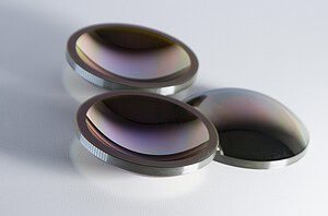
±0,03 mm. C'est la tolérance de précision de coupe sur les scies à fil continu Vimfun — et c'est un chiffre que nous garantissons pour les applications de verre, de céramique, de quartz et de saphir. Mais la tolérance sur une fiche technique et la précision sur une pièce finie ne sont pas la même chose. L'une est ce que la machine peut faire dans des conditions idéales. L'autre est ce que vous obtenez réellement, et cela dépend de tout, du diamètre du fil à la façon dont vous avez monté la pièce.
Cet article explique ce qui détermine la précision de la coupe au fil diamanté en pratique, ce qui peut la dégrader et comment maintenir un contrôle dimensionnel serré sur les séries de production.

Ce que signifie “ précision ” dans la coupe au fil diamanté
Lorsque les ingénieurs posent des questions sur la précision de la coupe au fil diamanté, ils s'interrogent généralement sur trois choses à la fois :
Précision dimensionnelle — la pièce finie correspond-elle aux dimensions cibles ? Si vous programmez une tranche de 10,00 mm d'épaisseur, obtenez-vous réellement 10,00 mm ? Cela dépend de la précision avec laquelle la système d'alimentation positionne la pièce et de la stabilité du fil pendant la coupe.
Uniformité de l'épaisseur — la tranche a-t-elle la même épaisseur de haut en bas, de gauche à droite ? Une tranche qui mesure 10,00 mm au point d'entrée mais 10,08 mm à la sortie a un problème de conicité. L'épaisseur moyenne peut être dans la cible, mais la pièce n'est pas vraiment précise.
Répétabilité — si vous coupez 20 tranches identiques dans le même bloc avec les mêmes paramètres, quelle variation observez-vous d'une pièce à l'autre ? Une tolérance serrée sur une seule coupe est utile. Une tolérance serrée sur une série de production est ce dont les environnements de production ont réellement besoin.
Ces trois aspects sont affectés par différents facteurs, c'est pourquoi l'amélioration de la précision de la coupe au fil diamanté nécessite une approche systématique plutôt que l'ajustement d'un seul paramètre.
Les facteurs qui déterminent la précision
Diamètre du fil et largeur de coupe
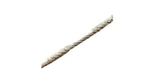
Le fil lui-même définit la largeur de coupe minimale réalisable — et donc l'espacement minimal entre les coupes. Un fil de 0,35 mm boucle en fil diamanté avec son revêtement diamanté produit une saignée d'environ 0,45 mm. Un fil de 0,8 mm produit une saignée d'environ 1,0 mm.
Pourquoi est-ce important pour la précision ? Parce que les fils plus fins fléchissent plus facilement sous la charge de coupe. Un fil de 0,35 mm se courbera sous la même pression d'avance qu'un fil de 0,8 mm ignore. La courbure du fil signifie que le chemin de coupe se courbe au lieu de rester droit, produisant un effilement — la tranche est plus mince à une extrémité qu'à l'autre.
Le compromis est simple : un fil plus fin économise plus de matière (saignée plus petite = moins de gaspillage) et permet des tranches plus fines, mais exige un contrôle des paramètres plus minutieux pour maintenir la précision. Pour les applications où la matière est coûteuse — germanium, saphir, silicium de haute pureté — les économies réalisées grâce à une saignée plus fine justifient souvent les efforts supplémentaires de développement du processus.
Pour la plupart des applications, nous recommandons de choisir le fil le plus fin qui maintient une courbure acceptable dans vos paramètres de fonctionnement. Commencez avec un diamètre plus grand, établissez vos paramètres de base, puis passez à un fil plus fin tout en surveillant l'effilement.‘

Tension du fil
Tension du fil a un effet direct et significatif sur la précision de la coupe au fil diamanté. Une tension plus élevée tire le fil plus droit, réduisant la courbure et améliorant la rectitude de la coupe. C'est le principal moyen de contrôle de l'effilement.
Plages de tension de travail typiques par matériau :
- Verre optique (BK7, K9) : 100–140 N
- Quartz (fusionné/cristal) : 150–200 N
- Céramique (alumine, zircone, SiN) : 150–200 N
- Matériaux magnétiques (ferrite, NdFeB) : 100–150 N
- Métaux poreux : 100–150 N
Mais il y a une limite. Poussez la tension trop haut et deux choses se produisent : premièrement, le fil se fatigue plus rapidement — la contrainte constante accélère l'arrachement des grains et la fatigue du fil central, raccourcissant considérablement la durée de vie du fil. Deuxièmement, sur certains matériaux, une tension excessive peut faire “s'enfoncer” le fil au point d'entrée, créant une surcoupe en haut de la tranche.
L'approche pratique : réglez la tension suffisamment haut pour maintenir la courbure dans votre tolérance, mais pas plus. Si votre tolérance est de ±0,05 mm sur une coupe de 50 mm de profondeur, vous n'avez probablement pas besoin de la tension maximale. Si vous maintenez ±0,03 mm sur une coupe de 100 mm de profondeur à travers de l'alumine frittée, vous serez proche du haut de la plage de tension — et vous accepterez le compromis sur la durée de vie du fil.
Débit d'alimentation
La vitesse d'avance est le deuxième contributeur majeur à la courbure du fil. Une vitesse d'avance plus rapide signifie une force de coupe plus importante sur le fil, ce qui pousse le fil vers l'arrière dans la coupe, créant un chemin de coupe courbe.
L'effet est proportionnel à la profondeur de coupe. Sur une coupe peu profonde de 10 mm, même des vitesses d'avance agressives produisent un arc minimal — la portée du fil est courte et rigide. Sur une coupe profonde de 100 mm, la même vitesse d'avance peut produire un arc important car la portée du fil non supporté est longue et flexible.
C'est pourquoi paramètres de coupe au fil diamanté pour les applications où la précision est critique, spécifiez généralement des vitesses d'avance plus faibles pour les coupes plus profondes. La règle générale : si votre tolérance est serrée et que votre profondeur de coupe est importante, la vitesse d'avance est la première chose à réduire.
Pour les matériaux comme saphir — qui est à la fois extrêmement dur et extrêmement précieux — les vitesses d'avance pour le tranchage de précision restent généralement dans la partie basse de la plage. Le taux d'enlèvement de matière par grain est élevé car le saphir est très dur, et chaque contact de grain génère une force de coupe importante. Une vitesse d'avance plus lente maintient cette force gérable et le trajet du fil droit.

Alignement des machines
C'est le facteur qui sépare une bonne précision d'une excellente précision — et il s'agit entièrement de la configuration mécanique, pas des paramètres de coupe.
Alignement de la machine englobe plusieurs éléments : le parallélisme des roues de guidage, le faux-rond des roues de guidage, la perpendicularité de l'axe d'avance par rapport au plan du fil, et la planéité de la table de travail. Si l'un de ces éléments est déréglé, aucun réglage de paramètre ne produira une coupe parfaitement droite et sans conicité.
L'alignement des roues de guidage est particulièrement critique. Les deux roues de guidage qui définissent la portée de coupe doivent être parfaitement parallèles et coplanaires. Si elles sont désalignées ne serait-ce que de 0,1 mm, le fil suit un trajet torsadé dans la zone de coupe. Le résultat est une surface de coupe qui n'est pas plate — elle présente une torsion hélicoïdale qui se manifeste par une variation d'épaisseur lorsque vous mesurez la tranche.
Nous avons vu des cas où un opérateur a passé des jours à ajuster la tension et la vitesse d'avance pour tenter d'éliminer une conicité persistante de 0,05 mm, pour découvrir qu'une roue de guidage s'était désalignée après un changement de roulement. Quinze minutes de correction d'alignement ont résolu ce que des heures de réglage de paramètres n'avaient pas pu faire.
Le message à retenir : si votre précision se dégrade soudainement après un événement de maintenance — remplacement de roulement, changement de roue de guidage, ou même une relocalisation importante de la machine — vérifiez l'alignement avant de toucher aux paramètres de coupe.
Fixation de la pièce
Le meilleur alignement de machine et les meilleurs paramètres de coupe du monde ne serviront à rien si la pièce bouge pendant la coupe.
La coupe au fil diamanté génère des forces de coupe relativement faibles par rapport aux scies à lame — généralement moins de 10 N de force apportée par la coupe elle-même. Mais c'est suffisant pour déplacer une pièce mal fixée, surtout vers la fin d'une coupe lorsque le pont de matière restant est mince.
Pour un travail de précision, la fixation doit :
- Maintenir la pièce de manière rigide contre toutes les forces de coupe (principalement vers le bas et dans la direction du déplacement du fil)
- Ne pas introduire de contrainte dans la pièce qui pourrait la faire fléchir lorsque la coupe la libère
- Permettre l'accès du liquide de refroidissement à la zone de coupe
- Être répétable pour le traitement par lots
Le montage à la cire est courant pour les petites pièces fragiles — ébauches de verre optique, substrats céramiques, fines plaquettes de saphir. La cire assure une tenue uniforme sans contrainte de serrage. Pour les pièces plus grandes, les fixations mécaniques avec une répartition adéquate de la force de serrage sont standard.
Un détail à noter : lors de la coupe de matériaux magnétiques comme le NdFeB, les copeaux magnétisés peuvent adhérer à la pièce et à la fixation, créant de fausses surfaces de référence pour les coupes ultérieures. Un nettoyage régulier entre les coupes est essentiel pour maintenir la précision sur un lot.

L'avantage de la boucle infinie pour la précision
L'architecture de la machine joue un rôle important dans la précision réalisable. Les scies à fil à boucle infinie ont un avantage structurel par rapport aux systèmes alternatifs.
Dans une scie alternative, le fil change de direction toutes les quelques secondes. À chaque inversion, le fil se détend brièvement avant d'être retendu dans la direction opposée. Pendant ce moment de détente, le fil peut se déplacer latéralement — surtout dans les coupes profondes où la portée du fil est longue. Chaque inversion introduit une petite incertitude de position.
Un scie à fil diamanté sans fin maintient une tension constante et une direction constante. Le fil ne se détend jamais. Il n'y a pas de mouvement latéral induit par l'inversion. La direction de la force de coupe est constante, ce qui signifie que la déformation du fil est constante et prévisible — vous pouvez en tenir compte dans votre configuration dimensionnelle plutôt que de traiter une variable aléatoire.
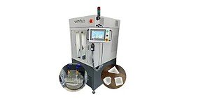
C'est l'une des raisons pour lesquelles la tolérance de ±0,03 mm est réalisable en pratique sur les machines Vimfun, pas seulement sur le papier. L'architecture unidirectionnelle élimine toute une catégorie d'incertitudes de position.
Problèmes de précision courants et leurs causes profondes
Taper (tranche plus épaisse à une extrémité qu'à l'autre). Cause profonde : déformation du fil due à une vitesse d'avance excessive, une tension insuffisante, ou les deux. Le fil se courbe loin de la direction d'avance, rendant le côté d'entrée plus épais que le côté de sortie. Solution : réduire d'abord la vitesse d'avance, puis augmenter la tension si nécessaire. Si le taper persiste, vérifiez l'alignement des roues guides.
Variation d'épaisseur sur un lot. Cause profonde : usure du fil. Lorsque le fil traverse plusieurs pièces, les grains de diamant s'usent et se détachent. Le diamètre effectif du fil diminue légèrement, ce qui modifie la largeur de coupe. Si vous utilisez le même décalage dimensionnel pour chaque coupe, les tranches ultérieures seront légèrement différentes des premières. Solution : surveiller la largeur de coupe périodiquement et ajuster le décalage d'avance pour compenser. Ou établir un calendrier de remplacement du fil qui garantit une largeur de coupe constante sur l'ensemble du lot.
Ondulation sur la surface de coupe. Cause profonde : vibration du fil due à des problèmes de roue de guidage, vitesse de fil élevée vitesse du fil amplifiant les imperfections mécaniques, ou roulements de roue de guidage usés. Solution : vérifier le faux rond de la roue de guidage (doit être inférieur à 0,05 mm), remplacer les roulements s'ils sont usés, réduire la vitesse du fil pour confirmer que le problème est lié aux vibrations.
Erreur de positionnement sur les coupes séquentielles. Cause profonde : dérive thermique ou jeu dans le système d'avance. Sur de longues séries de production, la température de la machine peut légèrement varier, provoquant une dilatation thermique de l'axe d'avance. Le jeu dans la vis mère introduit une erreur de positionnement lorsque le sens d'avance s'inverse entre les coupes. Solution : laisser la machine se stabiliser thermiquement avant de commencer les séries de précision. Pour les applications de grande valeur, vérifier les dimensions de la première et de la dernière coupe par rapport aux spécifications et ajuster en cours de série si nécessaire.
Éclats aux bords de coupe. Cause profonde : pas un problème de précision en soi, mais les éclats de bord modifient les dimensions effectives de la pièce finie, en particulier sur les tranches fines. Généralement causé par un taux d'avance excessif à l'entrée et à la sortie, ou par une coupe sans support adéquat côté sortie. Solution : réduire le taux d'avance au début et à la fin de chaque coupe (certaines machines prennent en charge des profils d'avance programmables), et s'assurer que la pièce est supportée des deux côtés de la coupe.
Jusqu'à quelle épaisseur peut-on couper avec précision ?
C'est l'une des questions les plus fréquentes que nous recevons. La réponse dépend du matériau, mais voici les limites pratiques basées sur notre expérience :
Jusqu'à environ 0,3 mm d'épaisseur, la plupart des matériaux peuvent être coupés de manière fiable avec un contrôle des paramètres standard. La tranche se détache du bloc intacte, conserve une planéité raisonnable et peut être manipulée sans outils spéciaux.
Entre 0,1 et 0,3 mm, le processus devient beaucoup plus exigeant. Vous avez besoin d'un fil plus fin (0,35 mm ou moins), d'une tension plus faible, d'un taux d'avance plus lent et d'un bridage très soigné. La tranche est fragile pendant et après la coupe — toute vibration ou tout déplacement peut la fissurer. Le bridage par aspiration ou le montage à la cire est presque obligatoire.
En dessous de 0,1 mm, c'est possible sur certains matériaux mais cela nécessite une configuration spécialisée et n'est pas une production de routine. À cette épaisseur, la flexibilité de la tranche devient un défi — la pièce peut fléchir pendant la coupe, rendant le contrôle de la précision dimensionnelle difficile.
L'idée clé : il ne s'agit pas seulement de savoir si vous pouvez couper aussi fin — il s'agit de savoir si vous pouvez le faire avec précision et répétabilité. Une tranche unique de 0,1 mm pour la R&D est réalisable. La production de 100 tranches consécutives de 0,1 mm avec une tolérance de ±0,03 mm est une autre discussion.
Surveillance du processus : détection précoce de la dérive de précision.
Pour les environnements de production où la précision de la découpe au fil diamant est essentielle sur de longues courses, la surveillance est primordiale. Les machines Vimfun prennent en charge la surveillance des processus qui suit les indicateurs clés pendant la découpe :
Tendance de la force de coupe. Si le courant du moteur d'avance augmente progressivement au fil du temps avec des paramètres constants, le fil s'use et l'efficacité de coupe diminue. C'est un indicateur précoce que la largeur de la saignée change et que la précision peut dériver.
Stabilité de la tension du fil. Des baisses soudaines de tension ou des oscillations peuvent indiquer un problème en développement — une roue de guidage desserrée, un défaut du fil ou un problème de roulement. Chacun de ces problèmes affectera la précision avant de causer un défaut visible.
Précision de la position d'avance. Le suivi de la position d'avance réelle par rapport à la position commandée identifie le jeu ou la dérive thermique dans le système de positionnement.
Détecter ces tendances tôt — avant qu'elles n'apparaissent sous forme de pièces hors spécifications — fait la différence entre la mise au rebut d'une pièce d'essai et la mise au rebut d'une production complète.
Étapes pratiques pour maximiser la précision
- Commencez par l'alignement. Avant toute optimisation des paramètres, vérifiez le parallélisme des roues de guidage, l'équerrage de l'axe d'avance et la planéité de la table de travail. Utilisez un comparateur, pas un jugement à l'œil. Ceci est non négociable pour un travail de ±0,03 mm.
- Choisissez le diamètre du fil en fonction de votre tolérance, pas seulement du coût. Un fil plus fin économise du matériau mais fléchit davantage. Adaptez le diamètre du fil à la profondeur de coupe et aux exigences de tolérance.
- Réglez la tension aussi haut que le permet la durée de vie du fil. Une tension plus élevée = des coupes plus droites. Mais surveillez attentivement la durée de vie du fil — il y a un point de rendement décroissant où une tension accrue n'aide guère la précision mais réduit considérablement la durée de vie du fil.
- Gardez un débit d'avance conservateur sur les coupes profondes. Pour un travail critique en matière de précision, privilégiez une vitesse d'avance plus lente, surtout lorsque la profondeur de coupe dépasse 50 mm.
- Fixez correctement la pièce. Un bridage rigide et répétable vaut le temps de mise en place. Montage à la cire pour les petites pièces fragiles, pinces mécaniques avec force répartie pour les pièces plus grandes.
- Surveillez et ajustez lors des séries de production. Ne réglez pas et n'oubliez pas — vérifiez les dimensions périodiquement et ajustez le décalage d'avance pour compenser l'usure du fil.
- Entretenez la machine. Les roulements des roues de guidage, les systèmes de lubrification, et les mécanismes de tension affectent tous la précision. Une machine bien entretenue maintient la tolérance ; une machine négligée dérive.
Pour une vue plus large de la façon dont la précision est liée à la qualité de la finition de surface, consultez notre guide sur la qualité du fil diamanté de coupe.
Ressource connexe sur le fil diamanté de coupe
Ce guide de précision soutient le plus large coupe du câble diamanté flux de travail.