Introduction: Tension Accuracy Defines Cutting Stability
In diamond wire cutting, wire tension is not just a parameter on the screen.
It is the mechanical foundation of geometric accuracy.
If the displayed tension value differs from the actual load applied to the wire, the entire cutting system operates on false assumptions. The result can include:
- Wire bowing
- Tapered cuts
- Surface waviness
- Premature wire fatigue
Wire tension calibration ensures that the control system reflects the true mechanical state of the wire. Monitoring ensures that this state remains stable during operation.
In precision applications such as silicon carbide, sapphire, quartz, and advanced ceramics, stable tension is directly linked to TTV and flatness performance.

1. Why Wire Tension Calibration Is Necessary
A tension system is not a static component. It drifts over time.
1.1 Sensor Drift
Load cells and pneumatic regulators gradually shift their zero reference due to:
- Thermal cycling
- Mechanical vibration
- Long-term material fatigue
Without recalibration, the controller may display 25 N while the actual tension is 22 N or 28 N.
1.2 Mechanical Hysteresis
Friction in:
- Dancer arm pivots
- Pulley bearings
- Pneumatic cylinder seals
creates deviation between theoretical and actual force. This mechanical resistance changes over time.
1.3 Error Amplification During Cutting
Even small tension errors increase wire bowing at entry.
As cutting depth increases, this deviation compounds and may lead to:
- Exit chipping
- Surface belly shape
- Wire snapping under load
Routine wire tension calibration prevents cumulative geometric instability.
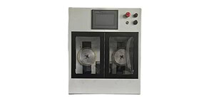
2. Types of Tension Measurement Systems
Understanding the sensing method is essential before calibration.
2.1 Pneumatic Pressure-Based Estimation
Some systems estimate tension based on air pressure.
Advantages:
- Simple
- Cost-effective
Limitations:
- Does not account for friction loss
- Typically ±2 N accuracy
Suitable for non-critical applications.
2.2 Load Cell (Direct Force Measurement)
Mounted beneath a tension pulley.
Advantages:
- Direct force reading
- High precision (±0.1 N possible)
- Stable long-term monitoring
This is the preferred method for precision slicing.
2.3 Displacement-Based Monitoring (Dancer Arm Position)
Measures angular movement of tension arm.
Useful for:
- Detecting elongation
- Monitoring dynamic behavior
However, absolute accuracy depends on system calibration.
3. Standard Wire Tension Calibration Procedure
Calibration must follow a physical verification process.
Step 1: Static Zero Check
- Remove the wire
- Ensure dancer arm moves freely
- Clean all pulleys
- Reset sensor zero
Zero reference must be stable before applying load
Step 2: Apply Certified Standard Weight
Use calibrated weights.
Formula:
Tension ≈ mass × 9.81
For 25 N target tension, use approximately 2.55 kg weight.
Suspend the weight through the pulley path to simulate actual load direction.
Step 3: Compare and Adjust
Record:
- Controller displayed value
- Theoretical value
Adjust:
- Offset (zero correction)
- Slope (gain correction)
Verify linear consistency across the operating range (e.g., 10–50 N).
4. Dynamic Tension Monitoring During Cutting
Static calibration is only half the process.
Real-time monitoring protects against failure.
4.1 Acceptable Fluctuation Range
Normal operating fluctuation:
±5% of setpoint
Example:
At 30 N setpoint → acceptable range 28.5–31.5 N.
4.2 Fluctuation Pattern Diagnosis
Different fluctuation patterns indicate different problems.
Slow drift:
→ Pneumatic leakage or regulator instability
Periodic oscillation:
→ Pulley eccentricity or mechanical imbalance
Sudden drop:
→ Partial strand failure or wire elongation
Tension monitoring should trigger alarm thresholds to prevent catastrophic breakage.
4.3 Pre-Breakage Indicators
When a wire begins to fatigue:
- Tension spikes become irregular
- Standard deviation increases
- Minor oscillations appear before failure
Monitoring variance is more useful than monitoring average value.
5. Common Calibration Mistakes
Ignoring Thermal Equilibrium
Calibration should be performed after machine warm-up.
Cold calibration may not reflect operating conditions.
Mixing Wire Diameters Without Rechecking
Different wire diameters sit differently in pulley grooves.
This changes effective lever geometry and sensor reading.
Recalibrate when changing wire diameter.
Over-Filtering Sensor Data
Excessive digital filtering smooths noise but reduces response speed.
A slow response increases risk of wire breakage under sudden load.
6. Recommended Calibration Interval
For precision applications:
Every 200 operating hours.
For heavy industrial applications:
Every 300–500 hours.
Calibration frequency should increase if:
- Wire breakage rate rises
- Surface stability decreases
- Tension readings fluctuate abnormally
Engineering Conclusion
Wire tension calibration is the foundation of mechanical stiffness control in diamond wire saw machines.
Accurate load measurement ensures:
- Reduced wire bowing
- Stable geometric accuracy
- Lower breakage rate
- Improved surface consistency
In precision slicing, tension monitoring is not optional.
It is part of the structural control system.
FAQ
Q1: Does calibration account for centrifugal force?
Static calibration does not. However, dynamic monitoring during low-speed testing verifies system behavior before full-speed operation.
Q2: How do I know if calibration solved a wire bow problem?
Perform a test cut and measure flatness. Reduced belly or taper indicates improved stiffness control.
Q3: Can tension be set higher to reduce bowing?
Higher tension increases stiffness but also reduces safety margin. Stability is more important than maximum tension.