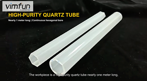
La ferrite est un matériau étrange à usiner. C'est techniquement une céramique — dure, cassante, électriquement non conductrice — mais c'est aussi le matériau d'aimant permanent le plus produit au monde. Des milliards de segments d'aimants en ferrite entrent chaque année dans les capteurs automobiles, les micro-moteurs, les haut-parleurs et les appareils électroménagers. Et chacun d'eux doit être découpé à partir d'un bloc fritté aux dimensions finales.
Le défi est que la ferrite ne coopère pas avec la plupart des méthodes de coupe conventionnelles. Elle se brise sous l'impact, s'écaille sur les bords tranchants et se fissure le long des joints de grains lorsqu'elle est soumise à des contraintes inégales. L'électroérosion ne fonctionne pas du tout car la ferrite est un isolant électrique. La découpe laser crée des fissures dues au choc thermique. Et le meulage abrasif, bien que possible, produit de graves dommages sous-jacents et génère des quantités massives de poussière fine.
Ce guide explique comment nous abordons la découpe de la ferrite avec scies à fil diamanté sans fin, ce qui la différencie de la découpe de NdFeB ou SmCo, et les choix de paramètres spécifiques qui contrôlent la formation de fissures et la qualité de surface.

Qu'est-ce qui rend la ferrite différente des autres matériaux magnétiques
Avant d'aborder les paramètres de coupe, il est utile de comprendre pourquoi la ferrite se comporte comme elle le fait sous un fil diamanté.
Les aimants permanents en ferrite — principalement la ferrite de strontium (SrFe₁₂O₁₉) et la ferrite de baryum (BaFe₁₂O₁₉), classés sous IEC 60404-8-1 pour les matériaux magnétiques durs — sont de véritables céramiques. Ils sont fabriqués en mélangeant de l'oxyde de fer avec du carbonate de strontium ou de baryum, en pressant et en frittant à 1200–1300 °C. Le résultat est une structure polycristalline avec une dureté Vickers d'environ HV 550–700, comparable au NdFeB mais avec une ténacité à la fracture significativement plus faible.
Cette faible ténacité à la fracture est la cause profonde de la plupart des problèmes de découpe de la ferrite. Là où le NdFeB pourrait tolérer une petite surcharge et s'écailler sur le bord, la ferrite propage des fissures profondément dans le corps. Une écaille de bord de 0,5 mm sur le NdFeB reste sur le bord. Un événement de contrainte similaire sur la ferrite peut envoyer une fissure de 5 à 10 mm dans la pièce, transformant un défaut de surface en une défaillance structurelle.
Trois propriétés clés façonnent la stratégie de coupe :
Non conductrice. La résistivité électrique de la ferrite est extrêmement élevée (10⁶–10⁸ Ω·cm), ce qui est en fait l'un de ses principaux avantages fonctionnels — de faibles pertes par courants de Foucault la rendent idéale pour les applications à haute fréquence. Mais cela signifie que la découpe par fil EDM est complètement exclue. Si votre ligne de production utilise l'EDM pour le NdFeB et que vous avez également besoin de découper de la ferrite, vous avez besoin d'une seconde technologie de coupe. Le fil diamanté fonctionne pour les deux.
Chimiquement stable. Contrairement au NdFeB, la ferrite ne s'oxyde pas à l'air humide ni ne se corrode dans les liquides de refroidissement à base d'eau. C'est un avantage pratique significatif lors de la découpe : vous pouvez utiliser un liquide de refroidissement à base d'eau ordinaire sans vous soucier de la dégradation de la surface. Pas besoin de liquide de refroidissement à base d'huile, pas de précipitation pour appliquer des revêtements protecteurs après la découpe, pas d'inhibiteurs de corrosion coûteux. Pour les ateliers traitant les deux matériaux, nous recommandons généralement un liquide de refroidissement à base d'eau pour les opérations sur ferrite et de passer à l'huile pour le NdFeB — consultez notre guide de refroidissement et de lubrification pour plus de détails sur la gestion des configurations à double liquide de refroidissement.
Structure de grains anisotrope. Les aimants en ferrite frittée sont pressés dans un champ magnétique pour aligner les grains cristallins. Cela crée une orientation préférentielle — l'axe magnétique — mais cela crée également une variation directionnelle des propriétés mécaniques. La découpe parallèle à l'axe d'alignement par rapport à la perpendiculaire produit une rugosité de surface et un comportement d'écaillage mesurables différents. Nous avons constaté des différences de Ra allant jusqu'à 30 % entre les deux orientations sur le même bloc, en utilisant des paramètres de découpe identiques.
Pourquoi les méthodes de découpe conventionnelles peinent avec la ferrite
Meules abrasives
C'est la méthode de production par défaut pour les fabricants d'aimants en ferrite. Les meules diamantées ou CBN enlèvent la matière rapidement et peuvent maintenir des tolérances raisonnables (±0,05 mm). Le problème est la force : les meules appliquent une force normale substantielle à la surface de la pièce, et la faible ténacité à la rupture de la ferrite signifie que les fissures sous-jacentes se propagent facilement sous cette force.
La zone de dommages sous-jacente sur la ferrite rectifiée s'étend généralement de 30 à 80 μm sous la surface — beaucoup plus profondément que ce que produit la découpe par fil diamanté. Pour les aimants destinés à des assemblages structurels ou à des applications de moteurs à haute fiabilité, ces dommages sous-jacents se traduisent par une réduction de la résistance mécanique et potentiellement des taux de rejet plus élevés lors des cycles thermiques.
Le meulage génère également d'énormes volumes de poussière fine de ferrite. Les particules sont inférieures à 10 μm, abrasives et se répandent partout. La gestion de la poussière sur les lignes de meulage de ferrite est un coût opérationnel majeur qui est souvent sous-estimé jusqu'à ce que le système de filtration doive être remplacé.
Découpe à lame à alésage intérieur
Les lames à alésage intérieur conviennent aux petits blocs de ferrite mais partagent le même problème fondamental que le meulage : les outils de coupe rigides appliquent des forces latérales que la ferrite ne peut pas tolérer. Les taux d'écaillage des bords supérieurs à 10 % sont courants, et la perte de matière due à l'épaisseur de la lame de 0,3 à 0,5 mm gaspille du matériau. Pour la production à haut volume de plaquettes minces de ferrite (moins de 3 mm), les taux de rejet de la découpe à la lame peuvent atteindre 15 à 20 % une fois que l'on tient compte de l'écaillage, des fissures et des pièces hors tolérance.
Découpe au jet d'eau
Le jet d'eau peut découper la ferrite sans dommages thermiques, et certains ateliers l'utilisent pour le prototypage ou les formes personnalisées. Mais les particules d'abrasif grenat créent un écaillage important sur les céramiques fragiles, et il est difficile d'obtenir un contrôle d'épaisseur constant. La saignée est également large — généralement de 0,8 à 1,5 mm — ce qui gaspille du matériau et limite l'épaisseur minimale de la tranche.

Comment la découpe par fil diamanté sans fin gère la ferrite
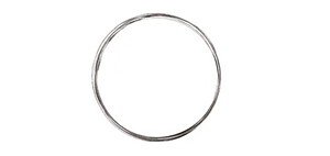
L'avantage fondamental de la découpe par fil diamanté pour la ferrite est la faible force de coupe. Le fil applique une force dans une seule direction, la zone de contact entre le fil et la pièce est une ligne mince (le diamètre du fil), et le mouvement unidirectionnel du boucle infinie élimine les chocs de renversement que les scies alternatives imposent.
Spécifiquement pour la ferrite, cela se traduit par :
Propagation de fissures réduite. La force maximale appliquée à la pièce à tout instant est d'un ordre de grandeur inférieure à celle du meulage. Les niveaux de contrainte restent inférieurs au seuil critique d'initiation des fissures dans la plupart des cas, ce qui empêche la formation de fissures plutôt que d'essayer de les gérer une fois qu'elles ont commencé.
Comportement de délaminage prévisible. Le délaminage des bords sur la ferrite coupée au fil est principalement contrôlé par la vitesse d'avance. En dessous d'un seuil spécifique au matériau (typiquement 2 à 3 mm/min pour les blocs de ferrite Sr standard), le délaminage côté sortie du fil tombe à près de zéro. Au-dessus de ce seuil, il augmente de manière prévisible, ce qui signifie que vous pouvez définir vos paramètres pour le niveau de qualité dont vous avez besoin.
Coupe fine. Avec un diamètre de fil de 0,35 à 0,50 mm, la perte de matière est d'environ 0,40 à 0,55 mm, soit environ la moitié de la coupe à la lame et une fraction de la découpe au jet d'eau. Pour la production d'aimants en ferrite où le coût du matériau est inférieur à celui du NdFeB, cela a moins d'importance par pièce. Mais pour la production de plaquettes minces (découpage d'un bloc en plusieurs morceaux), les économies cumulées s'accumulent. Un bloc de 50 mm découpé en plaquettes de 2 mm produit 17 pièces utilisables avec la coupe au fil contre 14 avec la coupe à la lame, soit une amélioration du rendement de 21 % due à la seule réduction de la perte de matière.
Paramètres de processus recommandés pour la ferrite
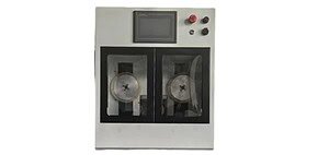
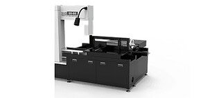
Sur nos SG20-R machines, nous utilisons ces paramètres typiques pour la ferrite frittée :
| Paramètre | Plage typique | Notes |
|---|---|---|
| Diamètre du fil | 0,35–0,50 mm | 0,35 mm pour les plaquettes minces, 0,50 mm pour un usage général |
| Vitesse du fil | 30–60 m/s | Une vitesse plus élevée améliore l'état de surface |
| Tension du fil | 100–130 N | Inférieur au NdFeB — la ferrite est plus sensible aux fissures |
| Vitesse d'alimentation | 1,0–2,5 mm/min | Conservateur pour la prévention des fissures |
| Liquide de refroidissement | À base d'eau | Aucune préoccupation d'oxydation avec la ferrite |
| Rugosité de la surface (Ra) | 0,4–0,8 μm | Dépend du débit d'avance et de l'état du fil |
Quelques notes sur ces chiffres :
La tension du fil est délibérément plus basse que pour le NdFeB. Nous utilisons généralement la ferrite à 100–130 N contre 100–150 N pour le NdFeB. La raison est la sensibilité à la fissuration — une tension plus élevée augmente la force de coupe à chaque point de contact du grain de diamant, ce qui, sur la ferrite, peut dépasser le seuil de fracture et initier des fissures sous-jacentes. Si vous observez des micro-fissures sur vos surfaces coupées (visibles sous un grossissement 20× comme de fines lignes perpendiculaires à la direction de coupe), la première chose à faire est de réduire la tension par incréments de 10 N.
Le débit d'avance a un seuil de qualité net. Avec le NdFeB, la qualité de surface se dégrade progressivement à mesure que le débit d'avance augmente. Avec la ferrite, il y a souvent une transition plus abrupte. En dessous de 2 mm/min, les surfaces sont propres avec un minimum d'écaillage. En passant à 3 mm/min, le taux d'écaillage augmente sensiblement. En passant à 4 mm/min et plus, vous commencez à obtenir des fissures sous-jacentes. Le seuil exact dépend de la section transversale du bloc, de la direction d'alignement des grains et de l'état du fil, mais le schéma est cohérent : la ferrite récompense des débits d'avance conservateurs plus que la plupart des autres matériaux.
Le liquide de refroidissement à base d'eau est standard. Comme la ferrite est chimiquement inerte à l'eau, il n'y a pas besoin de liquide de refroidissement à base d'huile. Le liquide de refroidissement à base d'eau fonctionne en fait mieux pour la ferrite car il dissipe la chaleur plus efficacement et produit une zone de coupe plus propre — les particules de poussière de ferrite sont facilement éliminées plutôt que de former une boue avec l'huile. Cela simplifie également considérablement le nettoyage après la coupe par rapport au traitement du NdFeB.

Prévention des fissures : le défi central
S'il y a une chose qui distingue la coupe de ferrite de tous les autres matériaux magnétiques, c'est la sensibilité à la fissuration. Comprendre comment les fissures se forment et se propagent lors de la coupe au fil diamanté est essentiel pour maintenir des taux de rendement acceptables.
Les fissures dans la ferrite coupée au fil proviennent de deux mécanismes :
Mécanisme 1 : Contrainte de traction à la sortie du fil. Lorsque le fil diamanté atteint le bord inférieur de la pièce, le pont de matériau restant s'amincit au point où il ne peut pas supporter la charge de coupe. Au lieu d'être coupé proprement, la dernière fraction de matériau se fracture — créant souvent une écaille ou initiant une fissure qui remonte dans le corps. C'est le même mécanisme qui provoque l'écaillage du côté de sortie dans tous les matériaux fragiles, mais la faible ténacité à la rupture de la ferrite aggrave le problème.
Prévention : Réduisez le débit d'avance pour les 2–3 derniers mm de chaque coupe. Sur nos machines, nous programmons un profil de débit d'avance à deux étages : débit d'avance normal pour la majeure partie de la coupe, puis une réduction de 50 % pour la zone de sortie. Certains opérateurs utilisent également une plaque de support sacrificielle — collée par adhésif au bas de la pièce — qui fournit un support matériel pendant la zone de sortie. Cette approche est empruntée à la découpe de plaquettes pratique et fonctionne bien pour les fines tranches de ferrite.
Mécanisme 2 : Libération des contraintes résiduelles. Les blocs de ferrite frittés contiennent des contraintes résiduelles provenant du processus de pressage et de frittage. Lorsque le fil coupe le bloc, il libère ces contraintes de manière asymétrique, ce qui peut provoquer un léger décalage des pièces coupées pendant la coupe. Si les pièces sont contraintes (par serrage), cette libération de contraintes crée des moments de flexion qui peuvent fissurer le matériau restant non coupé.
Prévention : Utilisez un bridage flexible qui permet un léger mouvement des pièces coupées. Le serrage rigide dans un étau est en fait pire pour la ferrite que pour le NdFeB, car il empêche la relaxation naturelle des contraintes qui se produit pendant la coupe. Le montage adhésif sur un substrat flexible, ou les pinces mécaniques à mâchoires à ressort, fonctionnent bien. Voir notre guide de conception de bridage pour des recommandations détaillées.
Qualité de surface sur ferrite coupée au fil
La morphologie de surface de la ferrite coupée au fil diffère du NdFeB de quelques manières importantes.
Le NdFeB possède une phase de joint de grain ductile riche en Nd qui permet un certain comportement de micro-coupe. La ferrite n'en a pas — c'est une céramique entièrement cassante. Cela signifie que le mécanisme d'enlèvement de matière est presque entièrement une fracture cassante à l'échelle du grain, avec très peu de micro-coupe ductile.
En pratique, cela se manifeste par :
Texture de surface plus uniforme. Paradoxalement, le mode de fracture entièrement cassante de la ferrite produit une surface plus homogène que l'enlèvement mixte ductile/cassant du NdFeB. La surface apparaît uniformément granulaire sous grossissement, sans les plateaux lisses entrecoupés de cavités de fracture qui caractérisent les surfaces coupées au NdFeB.
Valeurs Ra légèrement plus élevées. Parce qu'il y a un minimum de lissage ductile, les surfaces de ferrite coupées au fil diamanté présentent généralement des valeurs Ra de 0,4 à 0,8 μm contre 0,3 à 0,5 μm pour le NdFeB dans des conditions comparables. Pour la plupart des applications d'aimants en ferrite, cela est parfaitement acceptable — les aimants en ferrite reçoivent rarement un placage électrolytique (leur résistance à la corrosion le rend inutile), de sorte que les exigences de finition de surface sont moins strictes.
Arrachement de grain comme défaut dominant. Le défaut de surface le plus courant sur la ferrite coupée au fil est l'arrachement de grain entier : des grains de ferrite hexagonaux individuels (généralement de 1 à 5 μm de taille) se détachent aux joints de grains plutôt que d'être coupés. Cela crée de petites cavités qui contribuent à la rugosité de surface mais ne représentent pas de dommages structurels. Un arrachement de grain excessif (visible comme une surface crayeuse et poudreuse) indique que le fil est usé ou que le taux d'avance est trop élevé.
Ferrite vs. NdFeB : Différences clés dans l'approche de coupe
Pour les ateliers qui coupent les deux matériaux sur le même équipement, voici une comparaison pratique :
| Facteur | Ferrite | NdFeB |
|---|---|---|
| Liquide de refroidissement | À base d'eau (préféré) | À base d'huile (requis) |
| Tension du fil | 100–130 N (inférieur) | 100–150 N |
| Sensibilité au taux d'avance | Seuil de netteté (chute abrupte de la qualité) | Dégradation progressive |
| Risque de propagation des fissures | Élevé — les fissures pénètrent profondément | Modéré — les fissures restent sur les bords |
| Oxydation post-coupe | Aucune (stable chimiquement) | Rapide — protéger dans les 30 min |
| Revêtement post-coupe | Généralement inutile | Placage NiCuNi standard |
| rugosité de surface | Ra 0,4–0,8 μm | Ra 0,3–0,5 μm |
| Gestion de la poussière | Lavage à l'eau, filtration standard | Filtration d'huile, plus complexe |
| L'électroérosion comme alternative | Pas possible (non conducteur) | Possible (conducteur) |
La plus grande différence opérationnelle réside dans la gestion du liquide de refroidissement. Si vous passez de la ferrite aux aimants NdFeB sur la même machine, vous avez besoin d'une procédure de changement de liquide de refroidissement. L'utilisation de ferrite avec de l'huile résiduelle provenant de la découpe de NdFeB est acceptable — une petite quantité d'huile dans un liquide de refroidissement à base d'eau ne causera pas de problèmes. Cependant, l'utilisation de NdFeB avec de l'eau résiduelle provenant de la découpe de ferrite est risquée — même une trace d'humidité sur une surface NdFeB fraîchement coupée déclenche le processus d'oxydation. Nous recommandons de travailler d'abord la ferrite, puis de rincer et de passer à l'huile pour le NdFeB, plutôt que l'inverse.

Applications typiques de découpe de ferrite
Segments d'arc de moteur
L'application à plus grand volume pour l'usinage de ferrite. Les moteurs d'essuie-glace automobiles, les moteurs de lève-vitre, les moteurs de ventilateur CVC et les applications similaires utilisent des aimants en ferrite segmentés en arc. Ceux-ci nécessitent une épaisseur constante (±0,05 mm), des bords nets pour le collage aux boîtiers de moteur et un débit élevé. La découpe au fil diamanté gère le tranchage initial du bloc en segments, avec rectification pour le profil d'arc final si nécessaire.
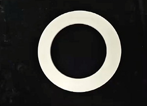
Aimants d'enceintes
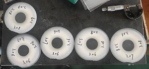
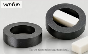
Les aimants en ferrite annulaires et disques pour les haut-parleurs nécessitent des faces planes et parallèles pour un assemblage correct du circuit magnétique. La découpe au fil produit le parallélisme nécessaire en une seule passe, éliminant souvent l'étape de rectification secondaire que requiert la découpe à la lame.
Aimants de capteurs
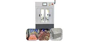
Petites pièces en ferrite pour capteurs de position, de vitesse et de proximité. Avec des dimensions comme 5 × 3 × 2 mm, la faible force de coupe du fil diamanté est essentielle — la coupe à la lame à ces tailles produit des taux d'écaillage inacceptables. Notre SG20 modèle de bureau gère bien ces applications de petites pièces, et le temps de configuration entre différentes tailles de pièces est minime.
Éducatif et prototypage
Les laboratoires de recherche et les équipes de développement de produits ont souvent besoin d'échantillons de ferrite coupés sur mesure pour des expériences de circuits magnétiques. La flexibilité de la coupe au fil — toute coupe droite à n'importe quelle épaisseur sans changement d'outil — la rend idéale pour les travaux uniques et les petites séries.
Problèmes et solutions courants de coupe de ferrite
Fissures apparaissant des heures après la coupe : Il s'agit presque toujours d'une libération de contraintes résiduelles. Le processus de coupe est propre, mais les contraintes résiduelles dans le bloc fritté se redistribuent après la coupe, provoquant des fissures retardées. Solution : utiliser une force de serrage plus faible et prévoir 24 heures de relaxation des contraintes avant l'inspection finale. Si les fissures retardées sont persistantes, le problème peut se situer en amont dans le processus de frittage — des taux de refroidissement inégaux pendant le frittage créent les contraintes résiduelles qui causent des problèmes lors de la coupe.
Surface de coupe crayeuse et poudreuse : Arrachement excessif des grains, indiquant généralement que le fil a dépassé sa durée de vie utile ou que le taux d'avance est trop élevé. Vérifiez d'abord l'état du fil — si le revêtement diamanté est visiblement usé ou inégal, remplacez le fil. Si le fil est neuf, réduisez le taux d'avance de 0,5 mm/min et réévaluez.
Écaillage asymétrique (un côté propre, l'autre côté écaillé) : Le côté propre est le côté d'entrée du fil ; le côté écaillé est la sortie. Ceci est normal à des taux d'avance plus élevés. Si cela est hors spécifications, réduisez le taux d'avance pour la zone de sortie, ou utilisez une plaque de support sacrificielle collée sur le côté de sortie.
Fissuration de la pièce pendant le serrage : La ferrite est suffisamment cassante pour que la seule pression de serrage puisse fissurer les ébauches minces. Utilisez des mors rembourrés (revêtement en caoutchouc ou en silicone) et évitez les pinces à contact ponctuel. Pour les tranches minces, le montage adhésif élimine entièrement les contraintes de serrage.
Qualité de surface incohérente sur la coupe : Souvent causé par une couverture de liquide de refroidissement inégale. Assurez-vous que le flux de liquide de refroidissement atteint les deux côtés de la zone de coupe. Une alimentation de liquide de refroidissement unilatérale crée des gradients thermiques et une évacuation inégale des copeaux., qui affectent tous deux la consistance de surface.
Démarrer avec la découpe de ferrite
Si vous évaluez la découpe par fil diamanté pour la production d'aimants en ferrite, la barrière à l'entrée est plus faible que pour le NdFeB. La stabilité chimique de la ferrite signifie que vous n'avez pas besoin de systèmes de refroidissement à base d'huile, de protection de surface post-coupe ou de procédures de nettoyage spécialisées. Un système de base SG20-R avec un liquide de refroidissement à base d'eau et un système standard fil diamanté électrodéposé gérera la plupart des applications de découpe de ferrite.
Nous proposons découpe d'essai gratuite pour les clients qui évaluent le processus — envoyez-nous vos échantillons de ferrite et nous les découperons avec des paramètres documentés afin que vous puissiez évaluer les résultats directement.