Алмазно-проволочная пила может производить поверхности NdFeB с шероховатостью Ra 0,3–0,5 мкм сразу после резки. Это хорошо выглядит на бумаге — и часто этого достаточно для магнитов, которые идут непосредственно в сборные узлы. Но для магнитов, предназначенных для гальванического покрытия или применений в прецизионных двигателях, “достаточно хорошо после пилы” и “готово к покрытию” — это два очень разных стандарта.
Зазор между этими двумя стандартами — это то, где происходит финишная обработка поверхности: снятие фасок, скругление кромок, шлифовка и этапы подготовки поверхности, которые определяют, будет ли ваше покрытие NiCuNi равномерно прилегать или отслаиваться в эксплуатации через шесть месяцев. Это руководство охватывает, что на самом деле включают в себя эти этапы, почему они важны именно для магнитных материалов и где алмазная резка проволокой уменьшает — или устраняет — объем последующей обработки после резки.

Почему финишная обработка поверхности для магнитов важнее, чем для большинства материалов
Спеченный NdFeB имеет микроструктуру, которая делает подготовку поверхности как более важной, так и более сложной, чем для твердых металлов.
Материал изготавливается методом порошковой металлургии. Процесс спекания неизбежно создает внутреннюю микропористость — крошечные пустоты, распределенные по всему объему материала, но сконцентрированные у поверхности. Когда вы режете или шлифуете материал, вы обнажаете эти поры. Это создает две последующие проблемы.
Во-первых, обнаженные микропоры удерживают загрязнители во время очистки и химии перед нанесением покрытия. Масло, остатки кислоты и промывочная вода проникают в поры за счет капиллярного действия и не выходят легко. Если эти загрязнители остаются при начале нанесения покрытия, они вызывают образование газовых пузырей под слоем покрытия, создавая поры, которые становятся очагами начала коррозии, когда магнит находится в эксплуатации.
Во-вторых, богатая Nd фаза на границе зерен на поверхности реагирует с влагой и кислородом. Эта реакция производит Nd(OH)₃ и рыхлые частицы оксида, которые находятся в поверхностных впадинах и порах. Если их не удалить перед нанесением покрытия, они образуют слабый граничный слой между подложкой и первым никелевым слоем. Результатом является плохое сцепление покрытия — покрытие выглядит хорошо визуально, но не проходит тесты на адгезию и в конечном итоге вздувается при термическом циклировании.
Именно поэтому производители магнитов серьезно относятся к подготовке поверхности. Резаная поверхность с Ra 0,5 мкм, но полная подповерхностных пор и оксидных загрязнений, будет покрываться хуже, чем шлифованная поверхность с Ra 1,0 мкм, которая была должным образом снята фаски и очищена ультразвуком.
Что дает алмазная резка проволокой — и чего она не дает
Давайте конкретно поговорим о состоянии поверхности, которое вы получаете от бесконечная алмазная проволочная пила.
При оптимизированных параметрах — скорость проволоки 30–60 м/с, скорость подачи 1,5–3,0 мм/мин, масляное охлаждающее вещество — типичная резаная поверхность спеченного NdFeB показывает:
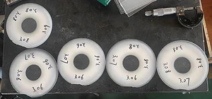
Шероховатость поверхности: Ra 0,3–0,5 мкм, иногда достигая 0,8 мкм на больших поперечных сечениях или при изношенной проволоке. Исследование MDPI Материалы измерило значения Ra в диапазоне от 0,43 мкм в оптимальных условиях до более 5 мкм при агрессивных скоростях подачи.
Морфология поверхности: Смесь микрорезных канавок (относительно гладкие площадки) и ямок хрупкого излома, где зерна Nd₂Fe₁₄B вырваны по границе раздела зерен. Соотношение гладкой и фрактурной площади сильно зависит от скорости подачи — более низкие скорости подачи приводят к большему количеству микрорезей и меньшему количеству ямок излома.
Волнистость: Периодические метки с интервалами, связанными с боковыми вибрациями проволоки. Значения PV (пик-долины) обычно составляют 3–15 мкм в зависимости от натяжения проволоки и состояния направляющего колеса. Эта волнистость является основной причиной того, что некоторые применения по-прежнему требуют легкой шлифовки после резки проволокой.
Подповерхностное повреждение: Минимальное по сравнению с резкой лезвием или электроэрозионной обработкой. Нет зоны термического влияния, нет переплавленного слоя. Подповерхностные микротрещины ограничены первыми 5–10 мкм при контролируемых параметрах резки.
Состояние кромки: Режущие кромки острые, углы 90 градусов. Нет встроенной фаски. Именно здесь после резки всегда требуется финишная обработка для покрытых магнитов, независимо от того, насколько хорошо выглядит поверхность резки.
Что проволочная пила НЕ дает вам: скругленные края, подходящие для гальванического покрытия, обезжиренную поверхность или удаление оксидной пленки, которая образуется на поверхности резки в течение нескольких минут после контакта с воздухом. Эти этапы требуют отдельных операций финишной обработки.
Фаски: Самый критический этап после резки
Если есть один этап финишной обработки поверхности, который нельзя пропустить для покрытых магнитов NdFeB, то это снятие фаски.
Причина — электрохимия. Во время гальванического покрытия силовые линии электрического поля концентрируются на острых углах и краях — это называется “эффектом наконечника”. На остром углу в 90 градусов толщина покрытия может быть в 2–3 раза больше номинальной спецификации, в то время как прилегающие плоские поверхности могут быть недопокрыты. Эта разница в толщине создает внутреннее напряжение в покрытии, а перепокрытые края становятся наиболее вероятными точками отказа.
Хуже того, хрупкие острые края NdFeB чрезвычайно подвержены микроскопическому сколу при обращении. Крошечный скол обнажает непокрытую подложку непосредственно к окружающей среде — а спеченный NdFeB быстро корродирует без защиты. Один сколотый угол может поставить под угрозу весь магнит.
Вибрационное снятие фаски
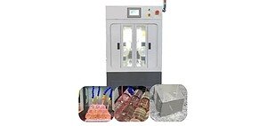
Самый распространенный метод для производственных партий. В вибрационную фаскоснимательную машину загружают заготовки NdFeB, абразивные материалы (зерна карбида кремния или коричневого корунда) и компаунд для снятия фаски. Вибрационный двигатель заставляет все элементы тереться друг о друга, постепенно скругляя края.
Типичное время цикла составляет 20–60 минут в зависимости от требуемого радиуса фаски и размера магнита. Процесс самоограничивается — после скругления краев дальнейшая обработка оказывает уменьшающееся воздействие. Абразивные материалы бывают разных размеров; более грубые зерна для агрессивного скругления краев, более мелкие зерна для сглаживания поверхности.
Ограничение: вибрационное снятие фаски также может незначительно снизить общую точность размеров. Для магнитов с жесткими допусками по толщине (±0,02 мм) необходимо учитывать снятие 0,02–0,05 мм материала с каждой стороны во время снятия фаски.

Бочковое (барабанное) снятие фаски
Принцип аналогичен вибрационному снятию фаски, но контейнер вращается вместо вибрации. Барабанное снятие фаски, как правило, более агрессивно и лучше подходит для небольших деталей из NdFeB (менее 15 мм по любому измерению). Центробежное прокатное действие быстрее скругляет края, но с меньшим контролем над конечной геометрией фаски.
Для очень маленьких магнитов (3 × 3 × 2 мм и аналогичных) барабанное снятие фаски является практически единственным практичным вариантом. Ручное снятие фаски при таких размерах невыносимо утомительно, и именно эти мелкие детали подвержены наибольшему риску сколов при обращении.
Механическое снятие фаски
Для более крупных магнитов или когда указан точный размер фаски (C0.2, C0.5, R0.3 и т. д.), фаска механически создается формованными шлифовальными кругами. Это обеспечивает лучший контроль размеров, но требует индивидуальной настройки для каждой детали и является более медленным для больших партий.
Мы видим, что механическое снятие фаски в основном используется на сегментах дуговых двигателей и крупных блочных магнитах, где размеры фаски указаны на чертеже заказчика и должны быть проверены измерением.
Шлифовка: когда поверхность после проволочной резки недостаточна
Самый частый вопрос, который мы получаем от новых клиентов, оценивающих алмазную проволочную резку: “Можем ли мы полностью отказаться от шлифовки?”
Честный ответ: зависит от вашего применения.
Применения, где поверхность после проволочной резки обычно достаточна (шлифовка не требуется):
Клееные сборки, где магнит приклеивается к корпусу. Поверхность Ra 0,3–0,5 мкм после проволочной резки обеспечивает отличную площадь для адгезивного соединения. Фактически, микрошероховатость после алмазной проволочной резки часто обеспечивает лучшую прочность клеевого соединения на сдвиг, чем шлифованная поверхность, поскольку ямки разрушения создают точки механического сцепления для клея.
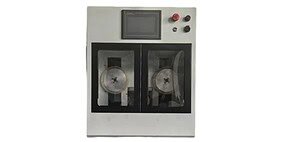
Магниты для сенсорных применений, где критическим размером является толщина, а допуск составляет ±0,05 мм или шире. Наша SG20-R проволочная пила обеспечивает повторяемость толщины в пределах ±0,03 мм по всей партии, что соответствует спецификациям для большинства заготовок сенсорных магнитов.
НИОКР и прототипирование, где чистота поверхности измеряется, но не является критерием прохождения/непрохождения.
Применения, где шлифовка все еще требуется после резки проволокой:
Высокопроизводительные магниты для двигателей, требующие Ra < 0,2 мкм и допуска по толщине ±0,01 мм. Эти характеристики достижимы, но выходят за рамки того, что может обеспечить любая проволочная пила напрямую.
Магниты с требованиями к плоскостности ниже 5 мкм TTV (общий перепад толщины) по всей поверхности. Поверхности, обработанные проволокой, имеют периодическую волнистость, которая обычно превышает это значение.
Большие объемы производства, где согласованность последующих процессов важнее, чем устранение одного этапа процесса. Некоторые производители двигателей предпочитают резать проволокой с припуском и шлифовать до конечного размера просто потому, что их процесс шлифовки статистически проверен, и они не хотят проводить повторную проверку.
Ключевой момент: алмазная резка проволокой значительно уменьшает количество материала, которое необходимо удалить при шлифовке. Поверхность, обработанная проволокой, обычно требует удаления 0,02–0,05 мм материала при шлифовке, по сравнению с 0,10–0,20 мм после резки лезвием. Это напрямую приводит к сокращению циклов шлифовки, меньшему износу шлифовального круга и снижению процента брака из-за термического повреждения, вызванного шлифовкой.

Очистка поверхности перед нанесением покрытия
Последовательность очистки между резкой/фаской и гальваническим покрытием — это то, где многие производители магнитов теряют качество. Проблема специфична для NdFeB: микропористая структура и реактивная фаза на границе зерен делают стандартные процессы обезжиривания и травления недостаточными.
Типичный процесс очистки перед нанесением покрытия для NdFeB включает:
Шаг 1: Ультразвуковое обезжиривание. Масляные смазочно-охлаждающие жидкости и составы для снятия фаски должны быть полностью удалены из поверхностных пор. Только погружного обезжиривания недостаточно — эффект ультразвуковой кавитации необходим для извлечения масла из микропор диаметром 1–10 мкм. Температура ванны 50–60 °C, продолжительность минимум 3–5 минут.
Шаг 2: Кислотное травление. Разбавленная кислотная ванна (обычно 2–5% азотной или лимонной кислоты) удаляет поверхностный оксид и тонкий обогащенный неодимом оксидный слой. Этот этап критичен по времени: слишком короткий — оксид остается, слишком долгий — кислота агрессивно атакует фазу на границе зерен, открывая новые поры и ослабляя поверхность. Большинство производителей нацеливаются на 30–90 секунд.
Шаг 3: Ультразвуковая промывка водой. Остатки кислоты должны быть вымыты из пор, прежде чем они вызовут дальнейшую коррозию. Многократные стадии промывки свежей деионизированной водой и ультразвуковой активацией.
Шаг 4: Активация слабой кислотой. Кратковременное погружение в разбавленную кислоту (обычно разбавленную HCl) непосредственно перед нанесением покрытия для обеспечения химической активности поверхности для первого никелевого покрытия.
Одна ошибка, которую мы видим постоянно: очистка деталей из NdFeB тем же методом, что и деталей из стали. Сталь непористая, поэтому погружная очистка работает нормально. Микропоры NdFeB действуют как крошечные резервуары — они впитывают чистящие химикаты и медленно выделяют их позже, загрязняя ванну для нанесения покрытия и вызывая дефекты покрытия. Ультразвуковая очистка на каждом этапе не является опцией для NdFeB.
Шероховатость поверхности и адгезия покрытия: взаимосвязь
Существует распространенное заблуждение, что для адгезии покрытия гладкость всегда лучше. На практике взаимосвязь между шероховатостью поверхности и адгезией покрытия на NdFeB более сложна.
Очень гладкие поверхности (Ra < 0,1 мкм, обычно после тонкого шлифования или притирки) на самом деле имеют более низкую механическую адгезию, поскольку текстура поверхности минимальна, за которую покрытие может “зацепиться”. Никелевый слой связывается в основном за счет химической адгезии на атомном уровне, которая сначала работает хорошо, но обеспечивает небольшое сопротивление отслаиванию при термических циклах.
Поверхности со средней шероховатостью (Ra 0,3–0,8 мкм, типично для алмазной проволочной резки) обеспечивают как химическую адгезию, так и механическое сцепление. Пики микрошероховатости и трещины создают точки опоры, которые значительно улучшают прочность на отслаивание. Это одна из причин, по которой поверхности, обработанные проволокой, иногда покрываются лучше, чем шлифованные поверхности — слегка более шероховатая, более текстурированная поверхность обеспечивает лучшую долговечность покрытия.
Очень шероховатые поверхности (Ra > 1,5 мкм, от агрессивной резки или изношенных инструментов) вызывают проблемы, поскольку долины поверхности слишком глубоки для равномерного заполнения покрытием. Покрытие следует топографии поверхности, создавая тонкие участки в долинах и толстые участки на пиках. При термических циклах дифференциальное тепловое расширение при этих изменениях толщины вызывает растрескивание.
Практическая цель для нанесения покрытия на NdFeB: Ra 0,3–1,0 мкм без отдельных поверхностных дефектов (царапин, забоин, кратеров вырывания зерен) глубиной более 10 мкм. Алмазная проволочная резка полностью соответствует этому диапазону при правильном контроле параметров процесса.

Параметры проволочной пилы, которые напрямую влияют на качество поверхности
Если вы режете NdFeB на бесконечной алмазной проволочной пиле и хотите оптимизировать качество поверхности, вот параметры, на которых следует сосредоточиться, в порядке их влияния:
1. Скорость подачи (самое сильное влияние). Исследования последовательно показывают, что скорость подачи является доминирующим фактором, контролирующим Ra на NdFeB. Снижение скорости подачи с 3,0 до 1,0 мм/мин обычно снижает Ra на 40–60%. Механизм прост: более низкая скорость подачи означает меньшую глубину резания на алмазный абразив, что обеспечивает большее снятие материала в режиме пластичного микрорезания, а не хрупкого разрушения.
2. Скорость проволоки. Более высокая скорость проволоки улучшает качество поверхности за счет увеличения количества зацеплений абразивных зерен на единицу длины реза. Переход от 20 до 60 м/с заметно снижает плотность ямок от изломов. Но выше 60 м/с улучшение прекращается, а износ проволоки ускоряется.
3. Состояние проволоки. Свежая проволока с неповрежденным алмазным покрытием обеспечивает наилучшее качество поверхности. По мере износа проволоки — алмазные зерна притупляются, некоторые зерна отрываются — шероховатость поверхности увеличивается. Отслеживайте суммарные метры резки и сопоставляйте их с измерениями качества поверхности, чтобы определить порог замены проволоки.
4. Состояние канавки ведущего колеса. Изношенные канавки позволяют проволоке колебаться в боковом направлении во время резки, создавая периодическую волнистость на поверхности реза. Если вы видите регулярные гребнеобразные узоры с интервалами 0,5–2 мм на поверхностях реза, проверьте канавки ведущего колеса, прежде чем корректировать другие параметры.
5. Поток охлаждающей жидкости. Достаточное количество охлаждающей жидкости в зоне резки смывает продукты резки и предотвращает повторное разрезание свободных частиц. Недостаточный поток охлаждающей жидкости приводит к внедрению частиц в поверхность реза, что проявляется в виде случайных царапин и повышенных значений Ra.
Когда следует рассмотреть альтернативные методы финишной обработки
Резка и снятие фаски алмазной проволокой решают большинство задач по финишной обработке поверхности NdFeB. Но некоторые специализированные применения требуют других подходов:
Притирка: Для требований к плоскостности оптического класса (< 1 мкм TTV). Используется в прецизионных датчиках магнитов и некоторых аэрокосмических применениях. Чрезвычайно медленно и дорого — оправдано только тогда, когда ничего другого не соответствует спецификации.
Бочковая полировка с мелкими абразивами: После снятия фаски второй проход с мелкими полирующими абразивами (керамические или пластиковые шарики) может снизить шероховатость поверхности до диапазона Ra 0,2 мкм без обеспечения такой же точности размеров, как при шлифовании. Полезно для декоративных магнитов или магнитов, используемых в медицинских устройствах, где указана гладкость поверхности.
Химическая или электрохимическая полировка: Редко используется на NdFeB, поскольку многофазная микроструктура травится неравномерно. Граничная фаза, богатая Nd, растворяется быстрее, чем основная фаза Nd₂Fe₁₄B, создавая преимущественную атаку по границам зерен, что фактически ухудшает целостность поверхности. Мы не рекомендуем этот подход, если только конкретное применение не было проверено.
Подготовка поверхности для конкретного покрытия: Некоторые передовые системы нанесения покрытий (физическое осаждение из паровой фазы, химическое осаждение из паровой фазы, атомно-слоевое осаждение) имеют свои собственные требования к подготовке поверхности, отличающиеся от гальванического покрытия. Если вы используете нестандартное покрытие, проконсультируйтесь с поставщиком покрытия по поводу спецификаций подготовки поверхности перед окончательным утверждением процесса финишной обработки.
Сборка воедино: Типичный технологический процесс
Вот как выглядит типичный процесс обработки детали из NdFeB от необработанного блока до покрытого готового магнита, с примечаниями о том, где вписывается резка алмазным проводом:
Спеченный блок из печи → Резка алмазным проводом (блок на срезы/заготовки) → Шлифовка (при необходимости для соблюдения допусков по размерам) → Фаски (вибрационная или барабанная обработка, 20–60 мин) → Ультразвуковая очистка (многоступенчатая) → Acid pickling (30–90 сек) → Промывка → Activation → Гальваническое покрытие (NiCuNi или Zn) → Финальная инспекция
Ключевой вывод из работы с сотнями производителей магнитов: оптимизация этапа резки проволоки сокращает или устраняет этап шлифовки, который является самой дорогой и медленной частью производственной цепочки. Хорошо настроенная SG20-R со свежей проволокой и правильным потоком охлаждающей жидкости обеспечивает заготовки, которые во многих случаях могут идти непосредственно на снятие фаски, полностью исключая шлифовку из процесса. Это обычно сокращает общее время и стоимость цикла обработки на 30–40%.
Для клиентов, рассматривающих этот подход, мы предлагаем бесплатная тестовая резка — отправьте нам ваши образцы NdFeB, и мы нарежем их с документированными параметрами, чтобы вы могли непосредственно оценить результаты.