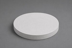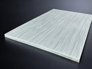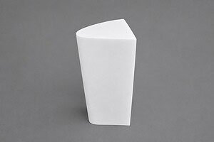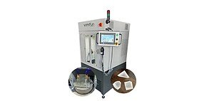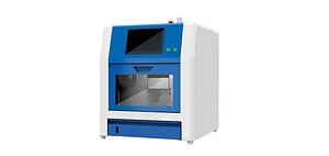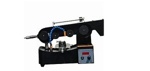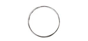
Custom shape diamond wire cutting uses a controlled abrasive wire path to create profiles that go beyond a basic straight separation cut. Depending on the machine axes, workpiece access and fixture, the process may produce external 2D profiles, internal contours, tapered sections or selected 3D surfaces in hard and brittle materials.
The wire is flexible, but it cannot turn an unlimited sharp corner or create every CAD shape directly. A workable design must account for wire diameter, abrasive envelope, machine motion, entry access, turning radius, cut depth and material fracture behavior. For equipment intended specifically for closed profiles, see the internal contour cutting machine.
What Counts as Custom Shape Cutting?
A custom shape may be defined by the outside profile of a block, an opening inside a part, a changing cross-section or a surface generated by coordinated machine motion. The correct method depends less on the appearance of the CAD model and more on how the wire can enter, remain supported and leave the workpiece.
| Shape type | Typical requirement | Main process constraint | Planning direction |
|---|---|---|---|
| External 2D profile | Outline cut through a plate or block | Corner radius, section depth, wire bow and edge support | Use a continuous open path and avoid abrupt direction changes |
| Internal closed contour | Opening or bore-like profile inside the workpiece | The wire needs an entry route and a compatible loop/threading method | Define the access hole, start point and closure workflow before programming |
| Tapered or angled profile | Different geometry between the top and bottom surfaces | Requires coordinated axes and control of wire inclination | Check machine travel, collision clearance and profile error through the depth |
| Selected 3D surface | Ruled or coordinated surface rather than a simple vertical wall | Machine-axis capability, wire contact and fixture accessibility | Validate the toolpath with the real machine kinematics, not CAD alone |
| Slots and repeated features | Multiple narrow cuts or indexed profiles | Part stiffness, cumulative positioning error and entry/exit damage | Plan feature order, support remaining walls and measure repeatability |
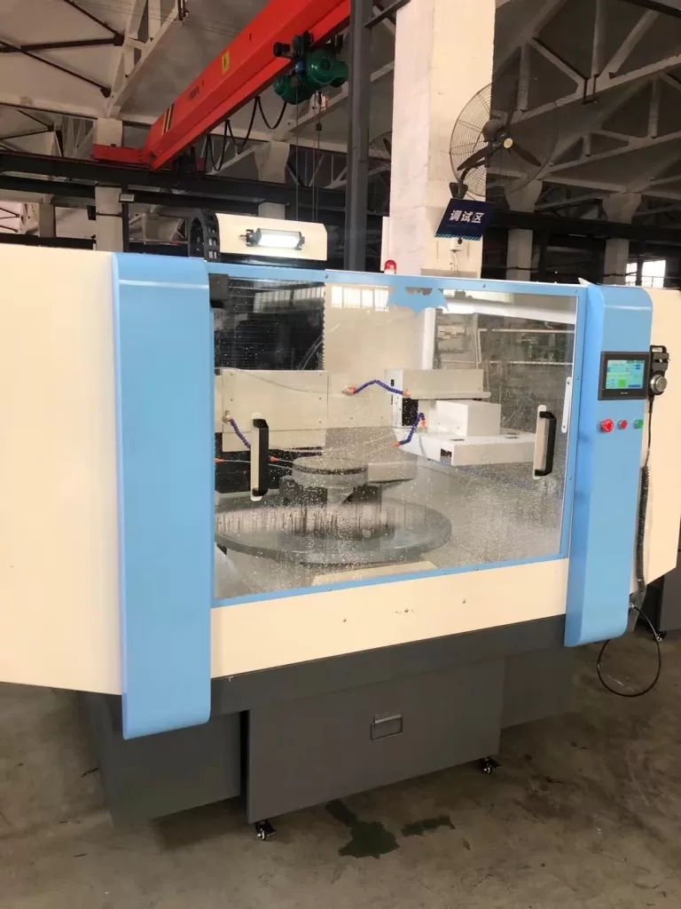
2D and 3D Wire Path Planning
CAD defines the target geometry, but the cutting program must translate that geometry into a path the wire and machine can execute. The programmed centerline should account for the actual kerf and any finishing allowance. Entry and exit moves should avoid fragile corners whenever possible.
- 2D profiles: normally use coordinated motion in a plane while maintaining a controlled wire path through the part thickness.
- Internal profiles: require a practical way to place the wire inside the intended opening before the closed path begins.
- 3D or tapered profiles: require machine axes capable of controlling the top and bottom path relationship without collision or excessive wire twist.
- Corner transitions: should be programmed with a radius and feed strategy that the wire, material and machine can follow consistently.
For an application-level overview of coordinated equipment, review multi-axis diamond wire saw applications. Final capability must still be confirmed against the selected machine model and workpiece dimensions.
Turning Radius, Kerf and Corner Accuracy
The minimum achievable internal radius is not equal to the bare wire radius. It is influenced by the abrasive envelope, wire stiffness, contact length, tension, feed, machine motion and the tendency of the material to chip. Tight corners also increase the risk that the wire cuts across the intended path or leaves a rounded transition.
Kerf compensation should be based on a representative test cut. The effective kerf can change with wire wear, runout, coating consistency, cut depth and process stability. Available wire diameters and coating structures are described on the diamond wire specification page, but catalogue diameter alone should not be used as the final toolpath offset.
Fixture, Entry Point and Workpiece Access
| Planning item | Risk if ignored | Practical check |
|---|---|---|
| Clamping area | Part movement, distortion or clamp marks | Support the part outside the toolpath and distribute force across stable surfaces |
| Remaining wall support | Thin features fracture or vibrate as material is removed | Choose the feature order and add sacrificial or backing support where appropriate |
| Entry and exit position | Visible edge chipping or an inaccessible start condition | Place transitions on less critical surfaces and confirm wire installation access |
| Wire clearance | Collision with fixtures, clamps or the workpiece | Simulate the complete wire and wheel path, not only the programmed contour |
| Datum strategy | Profile shift or cumulative error between features | Use repeatable locating surfaces and measure the part after critical stages |
| Debris removal | Loading, heat or particles trapped inside a closed kerf | Provide coolant access or dry extraction along the actual cutting zone |
Controlling Wire Wander and Surface Quality
Wire wander is a path error, not a single-setting problem. It can result from excessive feed, insufficient or excessive tension, worn abrasive, deep engagement, poor wheel alignment, weak support or abrupt direction changes. Surface marks may also follow loop inconsistency, vibration or trapped debris.
| Observed result | Possible causes to investigate | Adjustment direction |
|---|---|---|
| Profile cuts inside the programmed path | Insufficient kerf compensation, wire bow or aggressive corner transition | Measure actual kerf, reduce engagement and increase the programmed radius if needed |
| Taper through the thickness | Wire deflection, fixture tilt, path misalignment or uneven material contact | Verify datum, support and alignment before changing the toolpath |
| Chipping at a corner | Sharp direction change, unsupported edge or excessive local feed | Add a radius, support the edge and moderate motion through the transition |
| Periodic surface marks | Loop runout, vibration, wheel condition or inconsistent feed | Inspect the complete mechanical path and wire condition |
| Rough surface late in the cut | Debris accumulation, abrasive wear or increasing contact depth | Improve flushing/extraction and review staged feed through the section |
Material Differences in Custom Profiles
Silicon, quartz, glass, ceramics, graphite and composites do not respond to the same path or fixture strategy. Brittle materials need edge support and controlled transitions. Graphite requires dust management and attention to local density. Layered composites may delaminate or load the abrasive differently as the path crosses layers. Metals can impose different wear and chip-clearance demands.
A material name is not enough for process planning. Grade, density, dimensions, internal defects, coolant restriction and acceptance criteria should be supplied before the wire, machine and path are selected.
Complex Shape Cutting Application Video
The retained video demonstrates a specific cutting application. It is useful for observing the motion and workpiece setup, but it does not prove that the same path, radius or parameters can be transferred to another material or geometry.

Information Required for a Custom Shape Project
| Project item | Information to provide | Neden önemli |
|---|---|---|
| CAD and drawing | 2D drawing, 3D model, datums, tolerances and critical surfaces | Separates design geometry from measurable acceptance requirements |
| Malzeme | Exact grade, hardness or density, condition and internal defects | Influences abrasive choice, feed, chipping and fixture strategy |
| Workpiece | Overall dimensions, weight, available clamping surfaces and batch size | Determines machine travel, load, support and handling |
| Profile | Internal/external path, minimum radius, depth, entry hole and cut direction | Confirms whether the wire can access and follow the geometry |
| Quality target | Kerf allowance, profile tolerance, surface, chipping and finishing allowance | Defines how the test cut will be accepted |
| Process restriction | Wet/dry requirement, contamination, cleaning and dust-control limits | Guides wire coating and debris removal |
Sıkça Sorulan Sorular
Can diamond wire cut any shape drawn in CAD?
No. The design must be converted into a feasible wire path. Machine axes, wire access, minimum radius, workpiece support, cut depth and collision clearance limit what can be produced directly.
How is an internal closed contour started?
The wire needs an entry route inside the intended opening. The access hole, wire installation or loop-closing method and final start/stop area should be planned before machining.
What determines the minimum corner radius?
It depends on the abrasive envelope, wire stiffness, machine motion, tension, feed, contact depth and material behavior. A representative test is required before fixing a production tolerance.
Can one setup produce both 2D and 3D profiles?
Only if the machine has the required coordinated axes, travel and clearance. A machine designed for planar contouring should not be assumed to produce a controlled 3D surface.
What should be measured in a sample cut?
Measure actual kerf, profile error, corner radius, taper, straightness or flatness, surface condition and edge chipping. Record cycle time, wire condition, load behavior and fixture stability as well.
Sonuç
Custom shape diamond wire cutting begins with a feasible toolpath, not a promise that every CAD geometry can be cut. Reliable results require matching the profile to machine axes, wire access, turning radius, fixture support, material behavior and measurable quality targets. For broader machine architecture and selection after these requirements are defined, use the tel testere makinesi kılavuzu.