In high-value material processing, every extra 0.1 mm of wasted kerf width and every additional 0.1 μm of surface roughness directly consumes your profit margins. For production managers and quality engineers, the pursuit of optimisation de la qualité de surface is not merely an aesthetic requirement; it is a critical economic driver. In diamond wire cutting, the final output quality—measured primarily through surface topography and material yield—is the ultimate report card of your entire process configuration. All upstream variables, including wire speed, feed rate, cooling efficiency, and tension, converge into these two quantifiable results. Mastering the balance between throughput and precision is what separates a world-class manufacturing facility from an average one.
Section 1: Defining the Metrics — Ra, TTV, and Kerf Loss
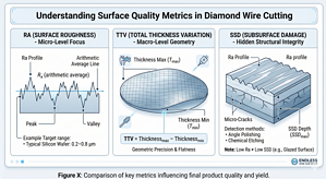
Before an engineer can optimize a process, they must establish a rigorous baseline for measurement. In diamond wire sawing, quality is defined by three primary geometric and topographic indicators.
1.1 Surface Roughness (Ra)
Le Ra value represents the arithmetic average of the microscopic peaks and valleys on the cut surface.
- Physical Meaning: It quantifies the micro-topography created by the individual diamond grits as they shear or fracture the material.
- Normes industrielles : For semiconductor-grade silicon, the typical target is 0,2–0,8 μm. For harder, more brittle materials like sapphire, the range often sits between 0,5–1,5 μm.
- Cost Impact: Higher Ra values indicate deeper “saw marks,” which require longer lapping and polishing cycles, increasing consumable costs and decreasing the final thickness of the part.
1.2 Total Thickness Variation (TTV)
While Ra measures micro-smoothness, TTV measures macro-geometric precision. It is the difference between the maximum and minimum thickness measured across a single sliced wafer or brick.
- Causes: High TTV is usually a symptom of wire instability, such as “wire bow” or high-frequency vibrations.
- Implications: Excessive TTV leads to uneven stress distribution during downstream processing, often resulting in cracked wafers during packaging.
1.3 Kerf Loss (Material Waste)
Kerf loss is the width of the material that is pulverized into powder (swarf) during the cutting process.
- Benchmarks: Moderne fil diamanté sans fin systems typically achieve kerf losses of 0,3–0,5 mm, whereas traditional band saws or inner-diameter saws can lose 1.5–3.0 mm.
- Yield Value: For materials like Silicon Carbide (SiC), reducing kerf by even 0,05 mm can result in several additional wafers per ingot, representing significant revenue gains.
Understanding the interplay between these metrics is essential. Reducing Ra often necessitates a lower feed rate, while minimizing kerf requires thinner (and thus more fragile) wires. Engineers must find the “Golden Ratio” of these parameters based on the principes du procédé de découpe au fil diamanté

Section 2: How Process Parameters Drive Surface Quality
Surface quality optimization is a multi-variant engineering challenge. No single parameter can be adjusted in a vacuum.
2.1 The Influence of Feed Rate
The feed rate is the primary driver of the “depth of cut” for each diamond grit.
- High Feed Rates: When the feed is too aggressive, the load on individual diamond particles exceeds the material’s elastic limit. This causes a transition from “ductile cutting” to “brittle fracture,” leading to deep gouges and a surge in Ra.
- Low Feed Rates: Conversely, an excessively low feed rate causes “rubbing,” where the diamond grits polish the surface instead of cutting it. This generates heat without removing material, leading to thermal damage.
2.2 The Influence of Wire Speed
Wire speed acts as the frequency modulator for the cutting event.
- Improved Ra: By increasing wire speed while maintaining a constant feed rate, the total number of diamond grits passing through the cut per second increases. This reduces the chip load per grit, leading to a smoother, more refined surface.
- The Vibration Threshold: However, exceeding the mechanical stability threshold of the machine induces “chatter” or harmonic resonance, which can paradoxically worsen surface roughness.
2.3 The Influence of Wire Tension
Tension is the “stiffness” of your cutting tool.
- Low Tension: Leads to wire bow, where the wire lags behind its drive pulleys inside the material. This creates a curved cut surface, resulting in poor TTV and “wavy” saw marks.
- High Tension: Improves geometric accuracy but increases the risk of wire fatigue and sudden breakage.
Optimizing these factors requires a deep dive into the relationship between feed rate and wire speed to ensure the wire remains in the optimal cutting regime throughout the entire cross-section.
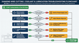
Section 3: The Role of Cooling in Surface Quality
One of the most common oversights in manufacturing is treating coolant as a secondary utility. In truth, cooling and lubrication in diamond wire cutting are foundational to surface integrity.
- Lubricant Film Stability: The cutting fluid creates a microscopic boundary layer between the wire core and the workpiece. Without this film, “dry friction” occurs, leading to micro-welding and thermal cracks on the surface.
- Swarf Evacuation: If the fine debris (swarf) is not immediately flushed from the kerf, it is “re-cut” by the passing wire. These trapped particles act as a secondary, uncontrolled abrasive that creates irregular scratches and degrades the Ra value.
- Thermal Consistency: Coolant temperature fluctuations cause the high-carbon steel wire core to expand and contract. This “thermal drift” changes the kerf width mid-cut, making it impossible to achieve low TTV.
Section 4: Kerf Loss Minimization — Engineering Strategies
Minimizing kerf loss is the most direct way to improve the “Material Utilization Rate” (MUR). In modern facilities, this is achieved through a combination of hardware and process strategy.
4.1 Downsizing Wire Diameter
Moving to thinner wires is the most effective way to reduce kerf.
- The 30% Rule: Reducing wire diameter from 0,5 mm à 0,35 mm theoretically reduces kerf loss by roughly 30%.
- Requirement: This transition necessitates ultra-sensitive, closed-loop servo tensioning systems to prevent the thinner core from snapping under load.
4.2 Eliminating Wire Bow
Wire bow occurs when the feed force exceeds the wire’s lateral resistance. A bowed wire creates a kerf that is wider than the wire’s actual diameter because of the side-to-side oscillation as it travels. By keeping the wire taut and the feed-to-speed ratio balanced, the “effective kerf” stays true to the wire diameter.
4.3 Abrasive Grit Selection
The size of the diamond grit electroplated onto the wire adds to the kerf. Finer grits (e.g., 10–20 μm) allow for narrower kerfs and better Ra but significantly slow down the Material Removal Rate (MRR).
| Wire Diameter (mm) | Diamond Grit Size (μm) | Typical Kerf Loss (mm) | Application |
| 0.12 – 0.20 | 10 – 20 | 0.15 – 0.25 | Semiconductor Slicing |
| 0.30 – 0.45 | 30 – 45 | 0.35 – 0.55 | Sapphire / Quartz |
| 0.50 – 0.80 | 50 – 70 | 0.65 – 1.00 | Ceramic / Metal Ingots |
Additionally, a rigorous analyse thermique dans le processus de découpe à froid is required to ensure that the heat-induced expansion of the wire doesn’t widen the kerf unintentionally.
Section 5: Subsurface Damage (SSD) — The Hidden Quality Killer
For semiconductor and optical applications, optimisation de la qualité de surface must extend beyond what is visible to the naked eye. Subsurface Damage (SSD) consists of micro-cracks and lattice distortions that penetrate deep into the material.
- The Invisible Cost: If the SSD is 20 μm deep, you must grind away at least 25 μm in the next step to ensure structural integrity. This is wasted material and wasted time.
- SSD vs. Ra: It is a common mistake to assume low Ra means low SSD. A “polished” looking surface created by a glazing wire can actually hide significant thermal cracks underneath.
- Optimization Strategy: To minimize SSD, one must control the “maximum grain depth of cut.” This is achieved by maximizing wire speed and maintaining a controlled, stable feed rate.
Reducing SSD is the ultimate goal of efficacité de coupe et durée de vie de l'outil programs, as it streamlines the entire production chain.
Section 6: Measurement and Quality Control Workflow
Data-driven optimization requires a standardized measurement protocol. You cannot manage what you do not measure accurately.
- Ra Measurement: Use a contact profilometer for daily floor checks. For R&D or high-precision batches, use a White Light Interferometer (WLI) to get a 3D topographic map of the surface.
- TTV Mapping: Utilize multi-point micrometer stations or automated laser thickness gauges. Map the TTV across the entire surface to identify if the error is occurring at the entry, middle, or exit of the cut.
- Kerf Verification: Periodically measure the remaining “stub” or use optical microscopes to verify that the kerf width matches the theoretical parameters.
- SPC Charts: Implement Statistical Process Control. If the Ra values start trending upward over a week, it is a leading indicator that your diamond wire is reaching its end-of-life or your coolant filtration system is failing.
By integrating surveillance en temps réel et contrôle des données, you can adjust parameters dynamically to compensate for tool wear, maintaining a constant quality level.

Questions fréquemment posées
Q1: What Ra value should I target for silicon wafer cutting?
Answer: This depends on your downstream process. If you have a robust lapping stage, 0.5–0.8 μm is standard. If you are moving directly to polishing, you should target < 0.3 μm to reduce polishing time and slurry consumption.
Q2: How much kerf loss is considered acceptable?
Answer: For endless diamond wire systems, the industry benchmark is 0,3–0,5 mm. In high-value sectors like SiC, anything above 0,25 mm is often targeted for further optimization to maximize the “wafer-per-inch” yield.
Q3: Can I improve surface quality without reducing throughput?
Answer: Yes, by increasing the wire speed (Vs) while keeping the feed rate (Vf) constant. This reduces the load per grit. Furthermore, optimizing your coolant formula can improve lubricity, leading to better Ra without slowing the machine down.
Q4: What causes inconsistent surface quality between cuts?
Answer: The three most common causes are:
- Coolant concentration drift (loss of lubricity).
- Wire degradation (the diamond grits have become rounded).
- Tension servo latency (causing micro-vibrations as the machine attempts to correct the tension).
Conclusion
Surface quality and kerf loss are the “final grades” on a diamond wire cutting process. Optimizing these metrics is not a matter of adjusting a single “knob” but rather a comprehensive engineering effort that synchronizes mechanical, thermal, and chemical variables. When you achieve optimisation de la qualité de surface, you are not just producing a better part; you are reducing material waste, lowering downstream costs, and increasing your facility’s total throughput.
Mastering these indicators is an ongoing journey. As diamond wire technology evolves toward thinner cores and more advanced coatings, the window for error shrinks. For more insights on the hardware capable of achieving these precision levels, visit our main page on coupe au fil diamanté.