Ein technisches Whitepaper für Diamantdrahtschneiden
Einleitung: Deterministische Fertigung und Ursachenanalyse
Probleme beim Präzisionsschneiden In der Ultrapräzisionsfertigung sind Fehler niemals zufällig; sie sind das Ergebnis physikalischer Variablen, die außerhalb der kontrollierten Prozessgrenzen liegen.
Zufälliges Versagen gibt es nicht.
Jeder Defekt, der auf einem geschnittenen Wafer beobachtet wird – sei es eine makroskopische Verjüngung, periodische Welligkeit oder mikroskopische Schäden unter der Oberfläche (SSD) – ist die deterministische Folge davon, dass eine oder mehrere physikalische Variablen außerhalb eines stabilen Prozessfensters liegen. Scheinbare Zufälligkeit ist lediglich auf mangelnde Messgenauigkeit oder unzureichendes Verständnis zurückzuführen.
Effektive Fehlersuche ist daher keine Frage von Versuch und Irrtum. Sie ist ein strukturierter Prozess in Variablenisolation, basierend auf mechanischer Dynamik, Tribologie und Regelungstechnik.
Dieses Whitepaper bietet einen Rahmen zur Ursachenanalyse für die Diagnose der häufigsten Fehlermodi in Diamantdrahtschneidsysteme. Jeder Abschnitt verknüpft beobachtbare Symptome mit zugrunde liegenden physikalischen Mechanismen und beschreibt Korrekturmaßnahmen, die die deterministische Prozesssteuerung wiederherstellen.
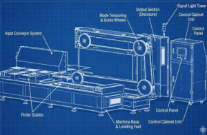
1. Mechanik der Drahtschwingungen: Die Physik des Ratterns
Die Drahtschwingung ist die Hauptursache für die Verschlechterung der Oberflächenwelligkeit (TTV) und die erhöhte Rauheit (Ra). Um sie korrekt zu analysieren, muss der Diamantdraht als … modelliert werden. gespannte Saite unterliegt den Gesetzen der Wellenmechanik.
1.1 Eigenfrequenz eines gespannten Drahtes
Die fundamentale Eigenfrequenz eines Drahtseils kann wie folgt ausgedrückt werden:
fn = (1 / (2 * L)) * sqrt(T / mu)
Wo:
- fn = Eigenfrequenz des Drahtes (Hz)
- T = dynamische Drahtspannung (N)
- L = Spannweite zwischen den Führungsrädern (m)
- μ = lineare Massendichte des Drahtes (kg/m)
Diese Beziehung zeigt, dass das Schwingungsverhalten des Drahtes vollständig deterministisch und durch Anpassung mechanischer Parameter einstellbar ist.
1.2 Harmonische Resonanz als Ursache
Resonanz tritt auf, wenn die Eigenfrequenz des Drahtes mit einer externen Anregungsquelle übereinstimmt, beispielsweise mit der Motorrotation, Lagerdefekten oder Antriebsstrang-Oberschwingungen. Die Rolle der kontinuierlichen, unidirektionalen Bewegung bei der Unterdrückung von Resonanz wird in unserem Artikel ausführlich erläutert. Ingenieuranalyse des Endlosschleifenschneidens.Unter Resonanzbedingungen steigt die Schwingungsamplitude sprunghaft an und erzeugt charakteristische Rattermarken auf der Schnittfläche.
Diagnose
- Verwenden Sie ein Stroboskop oder einen FFT-Schwingungsanalysator, um die dominanten Frequenzen zu identifizieren.
- Wenn die Schwingungsfrequenz mit der Motordrehzahl übereinstimmt (z. B. 50 Hz bei 3000 U/min), sind Unwucht oder antriebsbedingte Probleme wahrscheinlich.
- Wenn die Frequenz mit der berechneten Eigenfrequenz des Drahtes übereinstimmt, ist Resonanz bestätigt.
Korrektur
- Durch Anpassen der Drahtspannung (T) oder des Abstands der Führungsrollen (L) kann die Eigenfrequenz aus den Anregungsbereichen verschoben werden.
1.3 Rundlauffehler der Führungsrolle und lagerbedingte Geräusche
Ein Diamantdrahtsystem kann die Präzision seiner rotierenden Elemente nicht übertreffen.
Radialer Rundlauf
Ein Führungsrad mit einem Rundlauffehler von nur 10 Mikrometern erzeugt eine zyklische Auslenkung im Draht. Bei Drahtgeschwindigkeiten über 50 m/s wird dieses zu einer hochfrequenten Anregungsquelle.
Diagnose
- Messen Sie den gesamten angezeigten Rundlauf (TIR) mit einer Messuhr, die in die V-Nut eingesetzt wird.
- Ein akzeptabler TIR-Wert sollte unter 10 Mikrometern liegen.
Lagerverschleiß
Abgenutzte Lager erzeugen stochastische Vibrationen, die zu einer trüben Oberflächenstruktur anstelle regelmäßiger Wellenmuster führen.

2. Geometrische Ausrichtungsfehler: Verjüngung, Abweichung und Krümmung
Geometrische Fehler sind zwar statisch, akkumulieren sich aber über die Schnittlänge hinweg, was zu einer ungleichmäßigen Waferdicke führt.
2.1 Der Keileffekt (Verjüngung)
Symptom
Die Dicke der Wafer variiert linear von oben nach unten bzw. von links nach rechts.
Grundursache
Die Zuführachse verläuft nicht orthogonal zur Drahtstegebene.
Mechanismus
Sind die Führungsrollen nicht perfekt parallel, bildet der Drahtsteg eine verdrillte Oberfläche, die einer sattelförmigen Geometrie ähnelt. Beim Durchlaufen dieser verzerrten Ebene verschiebt sich der Materialabtrag schrittweise, wodurch eine Verjüngung entsteht.
Korrektur
- Führen Sie eine lasergestützte Ausrichtung der Führungsrollen durch.
- Die Parallelitätstoleranz sollte innerhalb von 0,02 mm pro Meter liegen.
2.2 Drahtdurchbiegung (Auslenkung)
Symptom
Die Schnittfläche ist in Vorschubrichtung gekrümmt, was gemeinhin als Bauch bezeichnet wird.
Körperliche Beziehung
Die Drahtdurchbiegung nimmt mit der Vorschubgeschwindigkeit zu und mit der Drahtspannung ab. Vereinfacht ausgedrückt:
Durchbiegung ~ Vorschubgeschwindigkeit / Drahtspannung
Korrekturmaßnahmen
- Durch Erhöhen der Drahtgeschwindigkeit lässt sich die Schnittkraft pro Schleifkorn verringern.
- Reduzieren Sie die Vorschubgeschwindigkeit während kritischer Schnittphasen.
- Prüfen Sie, ob das Spannsystem innerhalb seines effektiven Bereichs arbeitet.
3. Instabilität der Zuführung und das Stick-Slip-Phänomen
Symptom
Auf der Schnittfläche erscheinen horizontale Streifen, Stufenmarken oder Wasserzeichen, oft begleitet von einem pulsierenden Geräusch.
3.1 Tribologie von Linearführungen
Bei extrem niedrigen Vorschubgeschwindigkeiten (unter ca. 0,5 mm pro Minute) tritt beim Schneiden Grenzschmierung ein. Die Haftreibung übersteigt die Gleitreibung, wodurch die Vorschubachse abwechselnd klemmt und gleitet.
Jedes Gleitereignis erzeugt einen kurzzeitigen Anstieg der Chipbelastung, wodurch eine sichtbare Stufe auf der Waferoberfläche entsteht.
3.2 Steifigkeit des Servoregelkreises
Die Servoabstimmung bestimmt die Fähigkeit des Systems, Schwankungen der Schnittkraft bei gleichbleibender Geschwindigkeit zu widerstehen.
- Eine geringe proportionale Verstärkung ermöglicht Positionsverzögerungen und Welligkeit.
- Zu hohe Verstärkung führt zu Schwingungen und hörbaren Vibrationen.
Ingenieurprinzip
Servoregler sollten auf hohe Steifigkeit ohne grenzwertige Stabilität ausgelegt sein, um eine gleichmäßige Vorschubbewegung unter variabler Last zu gewährleisten.
4. Forensische Untersuchung von Drahtbrüchen: Die Bruchfläche analysieren
Die Bruchmorphologie eines gebrochenen Drahtes liefert einen direkten Beweis für den Versagensmechanismus.
4.1 Versagen durch Zugüberlastung
Erscheinungsbild
Verjüngung mit nadelartigem oder kegelförmigem Profil.
Auslegung
Übermäßige Spannung oder thermische Erweichung aufgrund von Kühlmittelmangel.
4.2 Ermüdungsversagen
Erscheinungsbild
Flache, glatte Bruchfläche senkrecht zur Drahtachse.
Auslegung
Zyklische Biegebeanspruchung, verursacht durch zu kleine Riemenscheiben oder verlängerte Lebensdauer.
4.3 Scherversagen
Erscheinungsbild
Die Bruchfläche ist in einem Winkel von etwa 45 Grad geneigt und weist häufig verschmiertes Material auf.
Auslegung
Plötzliche mechanische Einwirkung, Drahtentgleisung oder harte Einschlüsse im Werkstück.
5. Prozessdisziplin und deterministische Wiederherstellung
Die Präzisionsschneidleistung wird durch disziplinierte Iteration wiederhergestellt:
Beobachten
Hypothese aufstellen
Messen
Anpassen
Durch die Isolierung von Vibrationsquellen, die Überprüfung der geometrischen Ausrichtung und die Abstimmung der Servodynamik können Ingenieure ein deterministisches Verhalten in Diamantdrahtschneidsystemen wiederherstellen.
Präzision ist kein Zufall.
Es ist das Ergebnis von kontrollierten Variablen, die innerhalb bekannter physikalischer Grenzen wirken.
FAQ
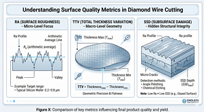
Frage 1: Worin besteht der Unterschied zwischen Sägespuren und Welligkeit?
Sägespuren sind hochfrequente Oberflächenrauigkeiten, die durch abrasive Wechselwirkungen oder Vibrationen verursacht werden. Welligkeit ist eine niederfrequente geometrische Verzerrung, die die Gleichmäßigkeit der Gesamtdicke (TTV) beeinträchtigt.
Frage 2: Warum erscheinen Eintrittsmarken auf SiC-Blöcken?
Eintrittsspuren entstehen durch den abrupten Übergang von berührungslosem zu flächigem Kontakt. Ein programmierter Sanftanlauf, der die Vorschubgeschwindigkeit für die anfängliche Schnitttiefe reduziert, minimiert diesen Effekt.
Frage 3: Wie oft sollten die Führungsrollen ausgetauscht werden?
Die Führungsrollen sollten alle 500 Betriebsstunden überprüft werden. Ist der Nutradius größer als der Drahtdurchmesser, erhöhen sich die seitlichen Vibrationen.