Introduction: The Physical Foundation of Slicing Accuracy
Proper machine alignment is the ultimate physical foundation for precision cutting in brittle materials like SiC and sapphire. In the manufacturing of these advanced ceramics, the accuracy of 다이아몬드 와이어 톱 기계 is determined long before the machine is powered on. Even the most advanced PLC programming cannot compensate for a twisted machine frame or misaligned pulleys.

1. Site Preparation and Initial Installation Steps
The installation of an industrial wire saw is not a simple “plug and play” operation. It requires a meticulously prepared environment to isolate the machine from external variables.
1.1 Foundation and Vibration Isolation
High-precision wire saws operate with microscopic tolerances. Therefore, the concrete foundation must be specifically designed to handle dynamic loads and absorb low-frequency vibrations from neighboring factory equipment.
- Concrete Thickness: The foundation should typically be at least 300 mm to 500 mm thick, depending on the machine’s total mass.
- Isolation Trenches: In facilities with heavy stamping presses or CNC milling centers, an isolation trench filled with vibration-dampening material (such as specialized sand or rubber padding) should surround the wire saw’s foundation.
- Curing Time: The concrete must be fully cured (usually 28 days) to prevent microscopic shifting after the machine is anchored.
1.2 Unpacking and Initial Positioning
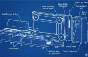
When moving the machine onto the foundation, it is critical to use the designated lifting points. Forklifts or overhead cranes must not apply pressure to the electrical cabinets, guide wheel shafts, or dancer arm assemblies. Once lowered onto the anchor points, the machine is ready for the first critical geometric adjustment.
2. The Precision Leveling Process
그만큼 leveling process is the single most important step in eliminating structural stress. If a machine chassis is bolted down unevenly, the cast iron or welded steel frame will experience torsion (twisting). This torsion translates directly into the guide wheel bearings, causing the cutting wire to jump during high-speed operation.
2.1 Tools Required for Machine Leveling
Standard bubble levels are insufficient for this task. Engineers must use:
- Master Precision Machinist Levels: Capable of measuring deviations as small as 0.02 mm/m.
- Laser Trackers or Optical Levels: For extra-long machines (such as multi-wire saws) to ensure the entire bed is perfectly flat.
2.2 Step-by-Step Leveling Execution
- Placement of Leveling Mounts: Position the heavy-duty leveling wedges or anti-vibration mounts under the designated load-bearing points of the chassis.
- Rough Leveling: Use a standard level to get the machine within a 1 mm/m tolerance.
- Cross-Hatch Measurement (Precision Leveling): Place the precision machinist level on the machined reference surfaces of the main base (usually the linear guide rail beds). Measure along the X-axis (parallel to the wire direction) and the Y-axis (perpendicular to the wire).
- Iterative Adjustment: Adjust the leveling bolts gradually. Because adjusting one corner affects the others, this is an iterative process. The goal is to achieve a levelness of 0.02 mm/m or better across all reference planes.
- Locking and Stress Release: Once the target is reached, lock the leveling nuts. Wait 24 hours for the mechanical stress in the frame to settle, then verify the levelness again before grouting or final anchoring.
3. Guide Wheel Alignment and Coplanarity
Once the base is perfectly level, the next phase of the machine alignment is ensuring that all guide wheels, tension pulleys, and the main drive wheel operate in perfect geometric harmony.
3.1 The Concept of Coplanarity
In a closed-loop endless wire saw, the diamond wire travels at speeds up to 60 m/s. For the wire to run smoothly, the V-grooves (or U-grooves) of all wheels in the wire path must be strictly coplanar—meaning they exist in the exact same mathematical plane.
If a guide wheel is angularly misaligned by even a fraction of a degree, the wire will climb the side of the groove before snapping back to the bottom. This micro-jumping causes:
- Severe surface waviness on the cut material.
- Rapid degradation of the polyurethane (PU) or rubber groove lining.
- Premature fatigue and breakage of the diamond wire.
3.2 Measurement and Alignment Techniques
Achieving a true precision setup requires specialized metrology:
- Dial Indicators (Dial Gauges): Mounted on a magnetic base, the indicator probe is placed against the side face of the guide wheel. As the wheel is manually rotated, the runout (axial wobble) is measured. It must be kept within the manufacturer’s strict tolerances (often < 0.01 mm).
- Straightedge and Feeler Gauges: A precision-machined straightedge is placed across the faces of multiple wheels to check parallel alignment.
- Laser Alignment Tools: A laser emitter is placed on the drive wheel groove, and targets are placed on the guide wheels. The laser beam instantly highlights any angular or parallel offset in the wire path.
3.3 Thermal Expansion Considerations
During alignment, engineers must account for factory temperature. A spindle operating at 4,000 RPM will generate heat, causing thermal expansion of the shaft and housing. Precision alignment should ideally be verified both in a “cold” state and after a thermal run-in period to ensure operational stability.
4. Integration with the Control System
Mechanical alignment and electronic control are inseparable. No software algorithm can fix a crooked pulley.
If the machine alignment is poor, the friction inside the pulley bearings and the lateral scraping of the wire will generate erratic force loads. This “mechanical noise” will be picked up by the tension sensors. As a result, the 장력 제어 시스템 will constantly overcorrect, leading to unstable pneumatic or servo responses.
Furthermore, executing a standard 와이어 장력 교정 is completely meaningless if the mechanical path is misaligned, because the friction losses will distort the static weight readings. Mechanical perfection must always precede electronic calibration.
5. Final Run-In and Vibration Analysis
After the leveling and alignment procedures are completed, the machine undergoes a critical run-in phase.
5.1 The Dry Run
The machine is powered on without cutting material. The wire speed is gradually increased from 10 m/s up to the maximum operational speed (e.g., 60 m/s). During this phase, engineers monitor the wire for visual stability (no excessive bowing or vibrating).
5.2 Vibration Diagnostics (FFT Analysis)
In high-end manufacturing, vibration sensors are attached to the spindle and guide wheel housings. Using Fast Fourier Transform (FFT) analysis, engineers can identify specific vibration frequencies.
- A high amplitude at the rotational frequency indicates an unbalanced wheel.
- High-frequency noise often points to a defective bearing or subtle misalignment. Only when the vibration signature falls within the acceptable baseline is the machine certified for production cutting.

Conclusion: The Cost of Ignoring Alignment
Skipping steps during the leveling process or rushing the guide wheel alignment is a guaranteed path to poor yield. In the 다이아몬드 와이어 커팅 industry, precision cannot be forced during the cut—it must be built into the machine before the wire ever touches the ingot. By committing to a strict precision setup, manufacturers ensure maximum wire lifespan, superior TTV, and long-term operational reliability.
자주 묻는 질문
1. How often should machine alignment be checked? For standard operations, alignment should be verified during major preventive maintenance cycles (e.g., every 6 months) or immediately after a severe machine crash or heavy component replacement.
2. Can I use a standard construction level for the leveling process? No. Standard construction levels lack the sensitivity required. A machinist level with a precision of 0.02 mm/m must be used to prevent micro-torsion in the machine bed.
3. What is the first sign of poor guide wheel alignment? The most common early indicator is uneven wear on the guide wheel grooves (wearing heavily on one side) or the sudden appearance of cutting marks (lines) on the surface of your wafers.