1,What Is a Wire Saw Machine?
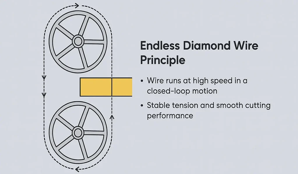
A ワイヤーソーマシン is a precision cutting system that uses a diamond-abrasive wire to slice hard and brittle materials with minimal mechanical stress.
It is built around a stable mechanical frame, a tension-regulated loop or reciprocating wire, and a high-precision feed system that ensures uniform cutting thickness and surface quality.
Typical applications include optical glass, ceramics, silicon, sapphire, graphite, and magnetic materials.
Mechanical Structure Overview
A wire saw machine consists of the following major assemblies:
2.1 Drive Wheel System
Supplies continuous motion to the diamond wire
Ensures constant linear velocity
Minimizes vibration and maintains cutting stability
2.2 Tensioning Wheel (Tension Arm Assembly)
Automatically compensates wire elongation
Maintains stable tension (150–250 N typical)
Prevents wire flutter and cutting deviation
2.3 Guide Wheel System
Aligns the wire path
Keeps the abrasive section engaging the workpiece precisely
Reduces kerf deviation and maintains uniform cutting thickness
2.4 Precision Feed Mechanism
Servo-controlled linear axis
Moves the workpiece toward the wire at micron-level increments
Determines final thickness, parallelism, and cut quality
2.5 PLC / Control Panel Unit
Houses machine settings, alarms, and wire-speed parameters
Provides operator interface
Integrates with sensors (tension, speed, feed, coolant)
3. Control System Architecture
Wire saw machines typically operate using a PLC-based control architecture, combined with feedback sensors to regulate cutting behavior.
3.1 PLC Control (Primary Mode)
Controls motor outputs and tension actuators
Monitors real-time parameters (speed, pressure, tension)
Provides safe, stable industrial operation
3.2 CNC or HL Control (Optional Secondary Mode)
Used for profile cutting or special motion patterns:
Supports multi-axis interpolation
Allows contour-based cutting paths
Enables independent feed control
3.3 Tension Feedback Loop
Air pressure or motor-based tensioning
Continuously checks wire load
Automatically adjusts to keep wire stable even during heavy cutting
4. 6. Wire Saw Machine Feed Motion Principles
Feed motion is critical for wire saw accuracy.
4.1 Servo-Controlled Automatic Feed
Smooth linear travel
Micron-level resolution
Ensures consistent removal rate
4.2 Constant Wire Speed + Adjustable Feed Rate
This pairing achieves:
Uniform thickness
Smooth cutting surfaces
Improved wire life
4.3 Equal-Thickness Cutting Mode
Some machines offer advanced features:
Automatic thickness compensation
Thickness uniformity below ±5–10 µm
Ideal for optical glass and ceramic substrates
5. Key Mechanical and Cutting Parameters
| パラメータ | Typical Range | 備考 |
|---|---|---|
| ワイヤースピード | up to 80 m/s | High speed reduces cutting force |
| ワイヤー径 | 0.30–0.80 mm | Determines kerf width and finish |
| Tension Force | 100–250 N | Critical for stable cutting |
| Feed Precision | ±2–5 µm | Depends on servo/guide system |
| Cutting Envelope | up to 200 × 200 mm | Model-dependent |
6. Wire Saw Machine Typical Application Materials
光学ガラス
Technical ceramics
Magnetic materials
シリコンとサファイア
黒鉛
Carbon composites
Polymer-on-glass diffusers
Advanced R&D samples
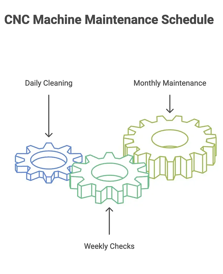
7. Wire Saw Machine Maintenance & Daily Care
Daily Cleaning
Remove debris from bellows covers, work table, and guide rails
Keep coolant or cutting oil clean
Weekly Checks
Inspect guide wheel wear
Check belt tension
Verify feed axis lubrication
Monthly / Periodic Maintenance
Replace wire grooves if vibration increases
Check all couplers and alignment
Calibrate tension and feed modules
8. Frequently Asked Questions
Q1. What is the difference between PLC and CNC control?
PLC focuses on stable industrial operation, while CNC provides multi-axis contour capability. Some machines combine both to support slicing and profile cutting.
Q2. How do I maintain wire tension stability?
Maintain clean guide wheels, replace worn grooves, and check tension feedback sensors. Unstable tension usually indicates wheel wear or incorrect groove geometry.
Q3. How is the feed movement calibrated?
Calibration is done via servo zeroing, travel compensation, and thickness measurement. Most modern machines allow direct calibration from the control panel.
Q4. What wire diameter should I choose?
0.30–0.35 mm for fine slicing;
0.40–0.60 mm for general materials;
0.65–0.80 mm for heavy, abrasive materials.
Q5. How do I know when the wire grooves need to be replaced?
Wire grooves should be replaced when you observe increased vibration at high wire speed (above ~3000 rpm equivalent), visible groove wear, or inconsistent cutting thickness. If the wire continues to vibrate after idle running and tension correction, the groove is the likely cause.
Q6. What installation conditions are required for a wire saw machine?
A stable foundation, 220–380 V electrical supply, clean coolant system, and proper ventilation are recommended. Machines must be leveled to maintain feed-axis accuracy, and ambient temperature should remain stable to avoid structural deformation.
Q7. What factors affect cutting flatness and parallelism?
Key factors include wire tension stability, feed-axis linearity, guide-wheel alignment, and material fixturing. Poor bonding of the workpiece to the baseplate is a common cause of thickness deviation in brittle materials.
Q8. Does wire diameter affect surface roughness?
Yes. Smaller diameters (0.30–0.35 mm) produce smoother surfaces and thinner kerf, while larger diameters (0.5–0.8 mm) improve wire life but may leave a slightly rougher finish. Material hardness and coolant type also influence final roughness.